


15 - 50
15. ABSOLUTE POSITION DETECTION SYSTEM
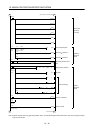
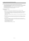
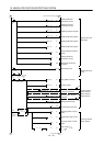
Note 1. For the dog type home position return. Need not be connected for the data set type home position return.
2. If the servo motor provided with the zero point signal is started, the A1SD75 will output the deviation counter clear (CR). Therefore,
do not connect the clear (CR) of the MR-J2-A to the A1SD75 but connect it to the output module of the programmable controller.
3. This circuit is provided for your reference.
4. The electromagnetic brake output should be controlled via a relay connected to the programmable controller output.
5. Use the differential line driver system for pulse input. Do not use the open collector system.
6. To reinforce noise suppression, connect LG and pulse output COM.
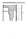
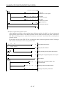
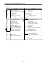
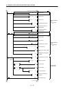
(2) Sequence program example
(a) Conditions
The ABS data is transmitted using the leading edge of the servo-on switch as a trigger.
1) When the servo-on switch and power supply GND are shorted, the ABS data is transmitted at
power-on of the servo amplifier or on the leading edge of the RUN signal after a PC reset
operation (PC-RESET). The ABS data is also transmitted when an alarm is reset or when an
emergency stop is reset.
Before starting the ABS data transfer, confirm that it is the servo-on (SON) ON state (refer to
section 3.3.2).
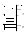
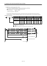
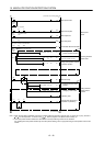
2) If a checksum mismatch is detected in the transmitted data, data transmission is retried up to
three times. If the checksum mismatch still persists after the retries, the ABS checksum error
occurs (Y3A ON).
3) The following time periods are measured. If the ON/OFF state does not change within the
specified time, the ABS communication error occurs change within the specified time, the ABS
communication error occurs (Y39 ON).
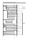
ON period of ABS transfer mode (Y31)
ON period of ABS request (Y32)
OFF period of reading to send ABS data (X22)