


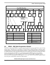
HDI08 – DSP-Side Programmer’s Model
DSP56366 24-Bit Digital Signal Processor User Manual, Rev. 4
6-8 Freescale Semiconductor
6.5.3.4 HCR Host Flags 2,3 (HF2,HF3) Bits 3-4
HF2 and HF3 bits are used as a general-purpose flags for DSP to host communication. HF2 and HF3 may
be set or cleared by the DSP core. HF2 and HF3 are reflected in the interface status register (ISR) on the
host side such that if they are modified by the DSP software, the host processor can read the modified
values by reading the ISR.
These two flags are not designated for any specific purpose but are general-purpose flags. They can be
used individually or as encoded pairs in a simple DSP to host communication protocol, implemented in
both the DSP and the host processor software.
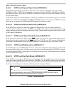
6.5.3.5 HCR Host DMA Mode Control Bits (HDM0, HDM1, HDM2) Bits 5-7
The HDM[2:0] bits are used to enable the HDI08 DMA mode operation. The HDI08 DMA mode supports
external DMA controller devices connected to the HDI08 on the Host side. This mode should not be
confused with the operation of the on-chip DMA controller.
With HDM[2:0] cleared, the HDI08 does not support DMA mode operation and the TREQ and RREQ
control bits are used for host processor interrupt control via the external HOREQ output signal (or HRREQ
and HTREQ output signals if HDREQ in the ICR is set). Also, in the non-DMA mode, the HACK input
signal is used for the MC68000 Family vectored interrupt acknowledge input. If HDM[2:0] are not all
cleared, the HDI08 operates as described in Table 6-5.
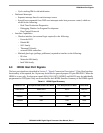
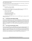
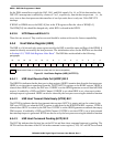
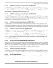
Table 6-4 HDI08 IRQ
Priority Interrupt Source
Highest Host Command (HCP=1)
Transmit Data (HTDE=1)
Lowest Receive Data (HRDF=1)
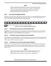
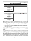
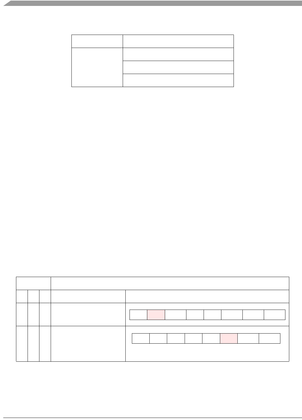
Table 6-5 HDM[2:0] Functionality
HDM Mode
2 1 0 Description ICR
0 0 0 DMA operation disabled
1 0 0 DMA Operation Enabled.
Host may set HM1 or HM0 in
the ICR to enable DMA
transfers.
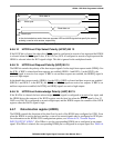
INIT HLEND HF1 HF0 HDRQ TREQ RREQ
INIT HM1 HM0 HF1 HF0 TREQ RREQ