


Operating Modes
DSP56366 24-Bit Digital Signal Processor User Manual, Rev. 4
Freescale Semiconductor 4-5
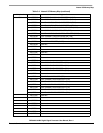
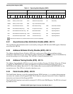
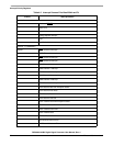
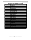
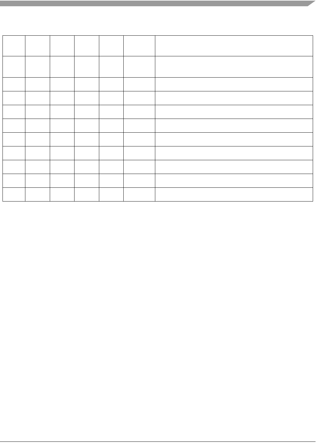
60110$FF0000Bootstrap from SHI (slave I
2
C mode) (HCKFR=1, 100ns filter
enabled)
70111$FF0000Bootstrap from SHI (slave I
2
C mode)(HCKR=0)
81000$008000 Expanded mode
91001$FF0000Reserved for Burn-in testing
A1010$FF0000Reserved
B1011$FF0000Reserved
C1100$FF0000HDI08 Bootstrap in ISA Mode
D1101$FF0000HDI08 Bootstrap in HC11 non-multiplexed mode
E1110$FF0000HDI08 Bootstrap in 8051 multiplexed bus mode
F1111$FF0000HDI08 Bootstrap in 68302 bus mode
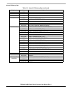
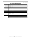
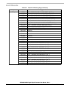
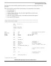
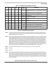
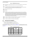
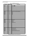
Table 4-3 DSP56366 Mode Descriptions
Mode 0 The DSP starts fetching instructions beginning at address $C00000. Memory accesses are performed using
SRAM memory access type with 31 wait states and no address attributes selected. Address $C00000 is reflected
as address $00000 on Port A pins A0-A17.
Mode 1 The bootstrap program loads instructions through Port A from external byte-wide memory, connected to the least
significant byte of the data bus (bits 7-0), and starting at address P:$D00000. The bootstrap code expects to read
3 bytes specifying the number of program words, 3 bytes specifying the address to start loading the program
words and then 3 bytes for each program word to be loaded. The number of words, the starting address and the
program words are read least significant byte first followed by the mid and then by the most significant byte. The
program words will be stored in contiguous PRAM memory locations starting at the specified starting address.
After reading the program words, program execution starts from the same address where loading started.The
SRAM memory access type is selected by the values in Address Attribute Register 1 (AAR1), with 31 wait states
for each memory access. Address $D00000 is reflected as address $00000 on Port A pins A0-A17.
Mode 2 The DSP starts fetching instructions from the starting address of the on-chip Program ROM.
Mode 3 Reserved.
Mode 4 Reserved.
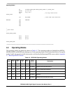
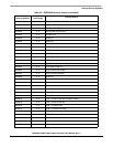
Mode 5 In this mode, the internal PRAM is loaded from the Serial Host Interface (SHI). The SHI operates in the SPI slave
mode, with 24-bit word width.The bootstrap code expects to read a 24-bit word specifying the number of program
words, a 24-bit word specifying the address to start loading the program words and then a 24-bit word for each
program word to be loaded. The program words will be stored in contiguous PRAM memory locations starting at
the specified starting address. After reading the program words, program execution starts from the same address
where loading started.
Table 4-2 DSP56366 Operating Modes (continued)
Mode
MOD
D
MOD
C
MOD
B
MOD
A
Reset
Vector
Description