


PLL Initialization
DSP56366 24-Bit Digital Signal Processor User Manual, Rev. 4
Freescale Semiconductor 4-13
4.6 PLL Initialization
4.6.1 PLL Multiplication Factor (MF0-MF11)
The DSP56366 PLL multiplication factor is set to 6 during hardware reset, i.e. the Multiplication Factor
Bits MF0-MF11 in the PLL Control Register (PCTL) are set to $005.
4.6.2 PLL Pre-Divider Factor (PD0-PD3)
The DSP56366 PLL Pre-Divider factor is set to 1 during hardware reset, i.e. the Pre-Divider Factor Bits
PD0-PD3 in the PLL Control Register (PCTL) are set to $0.
4.6.3 Crystal Range Bit (XTLR)
The Crystal Range (XTLR) bit controls the on-chip crystal oscillator transconductance. The on-chip
crystal oscillator is not used on the DSP56366 since no XTAL pin is available. The XTLR bit is set to zero
during hardware reset in the DSP56366.
4.6.4 XTAL Disable Bit (XTLD)
The XTAL Disable Bit (XTLD) is set to 1 (XTAL disabled) during hardware reset in the DSP56366.
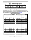
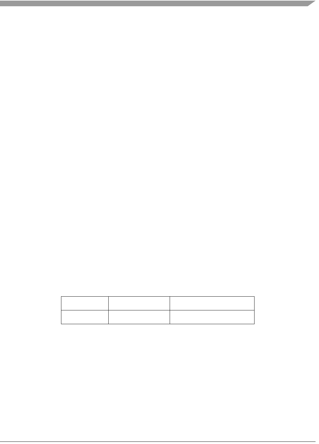
4.7 Device Identification (ID) Register
The Device Identification Register (IDR) is a 24 bit read only factory programmed register used to identify
the different DSP56300 core-based family members. This register specifies the derivative number and
revision number. This information may be used in testing or by software. Table 4-8 shows the ID register
configuration.
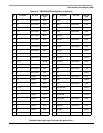
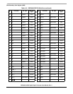
4.8 JTAG Identification (ID) Register
The JTAG Identification (ID) Register is a 32 bit, read only thought JTAG, factory programmed register
used to distinguish the component on a board according to the IEEE 1149.1 standard. Table 4-9 shows the
JTAG ID register configuration.
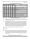
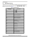
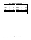
Table 4-8 Identification Register Configuration
23 16 15 12 11 0
Reserved Revision Number Derivative Number
$00 $0 $366