


DAX Signals
DSP56366 24-Bit Digital Signal Processor User Manual, Rev. 4
10-2 Freescale Semiconductor
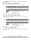
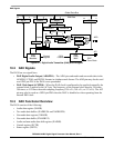
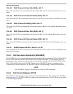
Figure 10-1 Digital Audio Transmitter (DAX) Block Diagram
10.2 DAX Signals
The DAX has two signal lines:
• DAX Digital Audio Output (ADO/PD1)—The ADO pin sends audio and non-audio data in the
AES/EBU, CP340, and IEC958 formats in a biphase mark format. The ADO pin may also be used
as a GPIO pin PD1 if the DAX is not operational.
• DAX Clock Input (ACI/PD0)—When the DAX clock is configured to be supplied externally, the
external clock is applied to the ACI pin. The frequency of the external clock must be 256 times,
384 times, or 512 times the audio sampling frequency (256 × Fs, 384 × Fs, or 512 × Fs). The ACI
pin may also be used as a GPIO pin PD0 when the DAX is disabled or when operating from the
internal DSP clock.
10.3 DAX Functional Overview
The DAX consists of the following:
• Audio data register (XADR)
• Two audio data buffers (XADBUFA and XADBUFB)
• Non-audio data register (XNADR)
• Non-audio data buffer (XNADBUF)
• Audio and non-audio data shift register (XADSR)
• Control register (XCTR)
• Status register (XSTR)
26
XSTR
C-U-V
PRTYG
Biphase
Encoder
Preamble
Generator
DAX
State
Machine
Control
Signals
XNADBUF
Global Data Bus
023
DAX
Clock
MUX
DSP
Core Clock
DAX
Clocks
XADSR
023
XNADR
23
Upload
MUX
MUX
MUX
23
00
XADR
XADBUFB
XADBUFA
DMA Bus
ADO
ACI
XCTR
0
23