


1
CONTENTS
1. FUNCTIONS AND CONFIGURATION 1- 1 to 1-18
1.1 Introduction.............................................................................................................................................. 1- 1
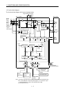
1.2 Function block diagram ..........................................................................................................................1- 2
1.3 Servo amplifier standard specifications ................................................................................................ 1- 3
1.4 Function list ............................................................................................................................................. 1- 4
1.5 Model code definition .............................................................................................................................. 1- 5
1.6 Combination with servo motor...............................................................................................................1- 6
1.7 Structure................................................................................................................................................... 1- 7
1.7.1 Parts identification ........................................................................................................................... 1- 7
1.7.2 Removal and reinstallation of the front cover .............................................................................. 1-11
1.8 Servo system with auxiliary equipment............................................................................................... 1-13
2. INSTALLATION 2- 1 to 2- 4
2.1 Environmental conditions.......................................................................................................................2- 1
2.2 Installation direction and clearances ....................................................................................................2- 2
2.3 Keep out foreign materials ..................................................................................................................... 2- 3
2.4 Cable stress .............................................................................................................................................. 2- 4
3. SIGNALS AND WIRING 3- 1 to 3- 58
3.1 Standard connection example ................................................................................................................ 3- 2
3.1.1 Position control mode .......................................................................................................................3- 2
3.1.2 Speed control mode...........................................................................................................................3- 6
3.1.3 Torque control mode.........................................................................................................................3- 8
3.2 Internal connection diagram of servo amplifier ..................................................................................3-10
3.3 I/O signals................................................................................................................................................3-11
3.3.1 Connectors and signal arrangements............................................................................................3-11
3.3.2 Signal explanations .........................................................................................................................3-14
3.4 Detailed description of the signals........................................................................................................3-23
3.4.1 Position control mode ......................................................................................................................3-23
3.4.2 Speed control mode..........................................................................................................................3-28
3.4.3 Torque control mode........................................................................................................................3-30
3.4.4 Position/speed control change mode .............................................................................................. 3-33
3.4.5 Speed/torque control change mode................................................................................................. 3-35
3.4.6 Torque/position control change mode ............................................................................................ 3-37
3.5 Alarm occurrence timing chart ............................................................................................................. 3-38
3.6 Interfaces.................................................................................................................................................3-39
3.6.1 Common line ....................................................................................................................................3-39
3.6.2 Detailed description of the interfaces............................................................................................ 3-40
3.7 Input power supply circuit.....................................................................................................................3-45
3.7.1 Connection example.........................................................................................................................3-45
3.7.2 Terminals.......................................................................................................................................... 3-47
3.7.3 Power-on sequence...........................................................................................................................3-48
3.8 Connection of servo amplifier and servo motor ...................................................................................3-49
3.8.1 Connection instructions ..................................................................................................................3-49