


3 - 2
3. SIGNALS AND WIRING
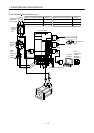
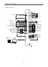
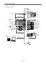
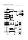
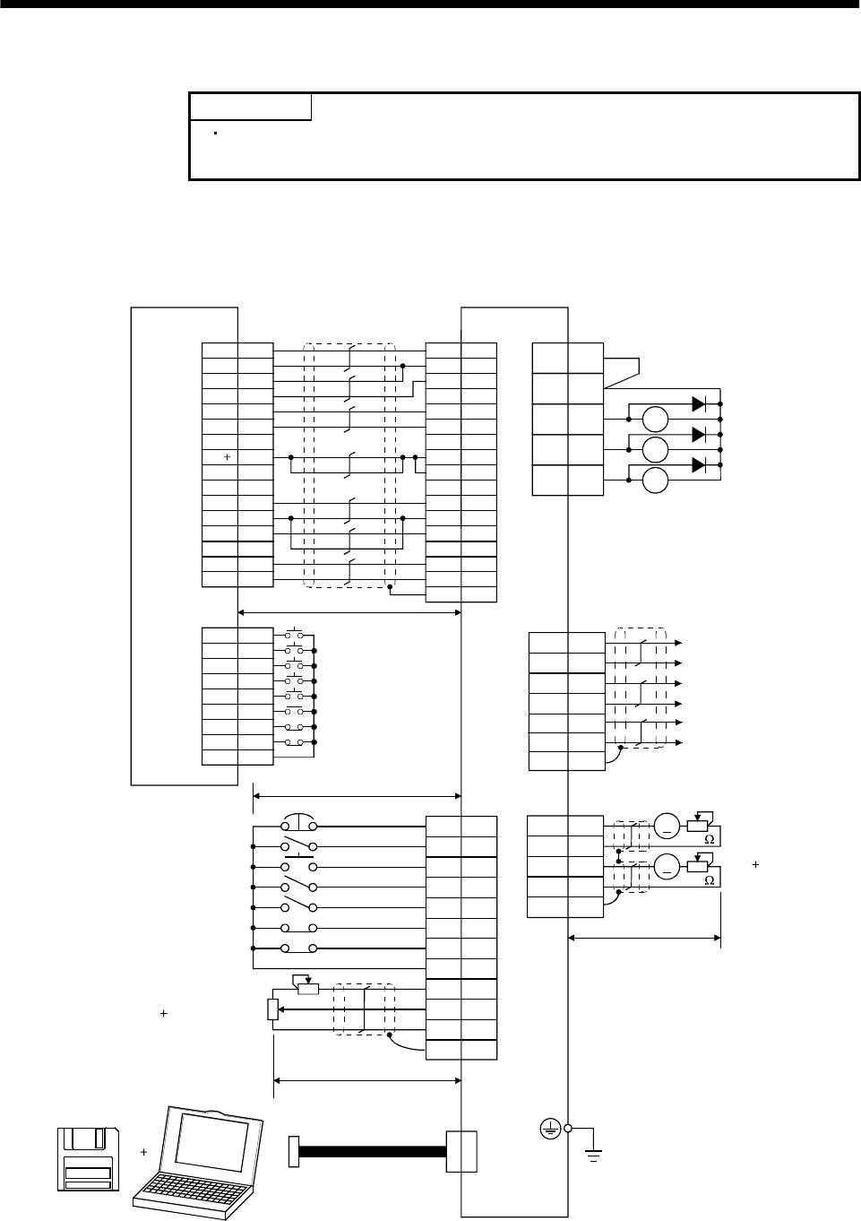
3.1 Standard connection example
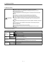
POINT
Refer to Section 3.7.1 for the connection of the power supply system and to
Section 3.8 for connection with the servo motor.
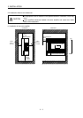
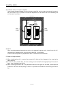
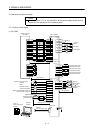
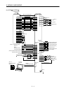
3.1.1 Position control mode
(1) FX-10GM
VDD
RA1
RA2
RA3
18
15
5
14
8
9
16
17
12
EMG
SON
RES
PC
TL
LSP
LSN
SD
SG
P15R
LG
10
11
ALM
19 ZSP
6TLC
CN1B
13 COM
3
TLA
CN1A
4
13
3
SD
LG
14
MO1
LG
MO2
CN3
A
A
18
19
9
4
14
1
11
9
3
10
2
8
20
START
STO
FWD
RVS
DOG
LSR
COM1
1
2
4
5
6
8
9,19
3
7
ZRN
LSF
FX-10GM
1
CN3
Positioning module
SVRDY
COM2
COM2
SVEND
COM4
PG0
24
VC
FPO
FP
COM5
RP
RP0
CLR
4
(Note 3, 6) Emergency stop
Servo-on
Reset
Proportion control
Torque limit selection
(Note 6) Forward rotation stroke end
Reverse rotation stroke end
Upper limit setting
Analog torque limit
(Note 11)
Servo configuration
software
Personal
computer
10V/max. torque
(Note 10) 2m(6.5ft) max.
10m(32ft) max.
2m(6.5ft) max.
(Note 8)
Communication cable
Servo amplifier
(Note 4, 9) (Note 4)
CN1A CN1B
1
2
12
11
14
13
7,17
8,18
5
6
9,19
16
15
3
(Note 12)
(Note 2, 5)
(Note 7)
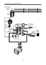
Trouble
Zero speed
Limiting torque
(Note 4, 9)
7
6
16
Plate
17
LB
LA
LAR
SD
LBR
Encoder A-phase pulse
(differential line driver)
Encoder B-phase pulse
(differential line driver)
(Note 4, 9)(Note 4, 9)
Plate
Plate
(Note 8)
Monitor output
Max. 1mA
Reading in both
directions
10k
10k
2m (6.5ft) max.
(Note 4, 9)
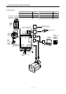
(Note 1)
Plate
RD
COM
INP
P15R
OP
LG
COM
PP
SG
NP
CR
SD
SG
COM3
OPC
(Note 13)
5
15
LZ
LZR
Encoder Z-phase pulse
(differential line driver)