


3 - 39
3. SIGNALS AND WIRING
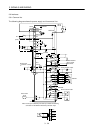
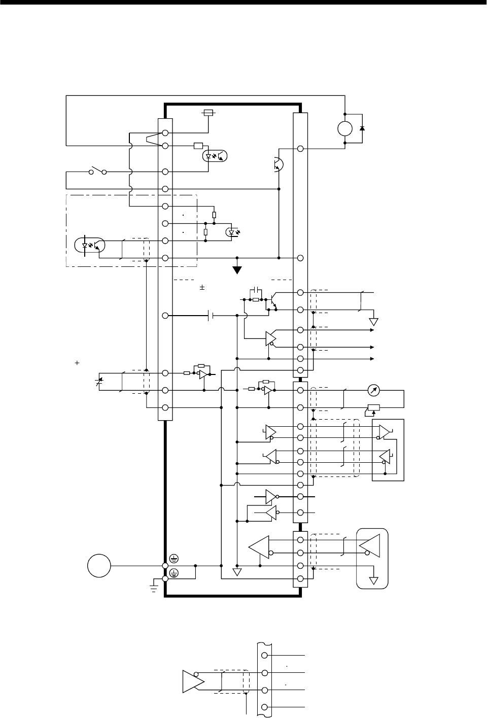
3.6 Interfaces
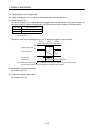
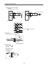
3.6.1 Common line
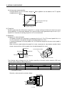
The following diagram shows the power supply and its common line.
DC24V
CN1A
CN1B
CN1A
CN1B
DO-1
SG
OPC
PG NG
SG
P15R
LG
TLA
VC etc.
SD
OP
MR
MRR
SM
DI-1
COM
VDD
ALM .etc
LG
SD
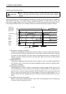
RDP
RDN
SDP
SDN
LG
CN3
RA
CN2
SD
MO1
MO2
LG
SG
TXD
RXD
RS-232C
RS-422
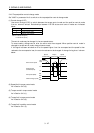
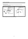
(Note)
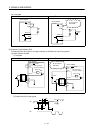
Analog input
( 10V/max. current)
Servo motor
Ground
SD
LG
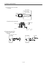
Servo motor encoder
Isolated
15VDC 10%
30mA
LA etc.
Analog monitor output
SON, etc.
PP NP
LG
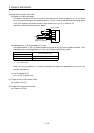
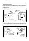
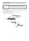
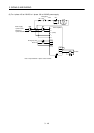
Note: For the open collection pulse train input. Make the following
connection for the different line driver pulse train input.
Differential line
driver output
35mA max.
LAR
etc.
SG
PP NP
PG
NG
OPC