


13 - 29
13. OPTIONS AND AUXILIARY EQUIPMENT
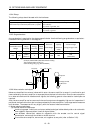
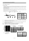
13.2.4 Relays
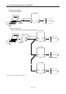
The following relays should be used with the interfaces:
Interface Selection example
Relay used especially for switching on-off analog input
command and input command (interface DI-1) signals
To prevent defective contacts , use a relay for small signal
(twin contacts).
(Ex.) Omron : type G2A , MY
Relay used for digital output signals (interface DO-1) Small relay with 12VDC or 24VDC of 40mA or less
(Ex.) Omron : type MY
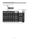
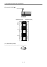
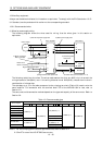
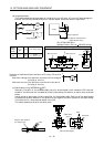
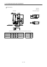
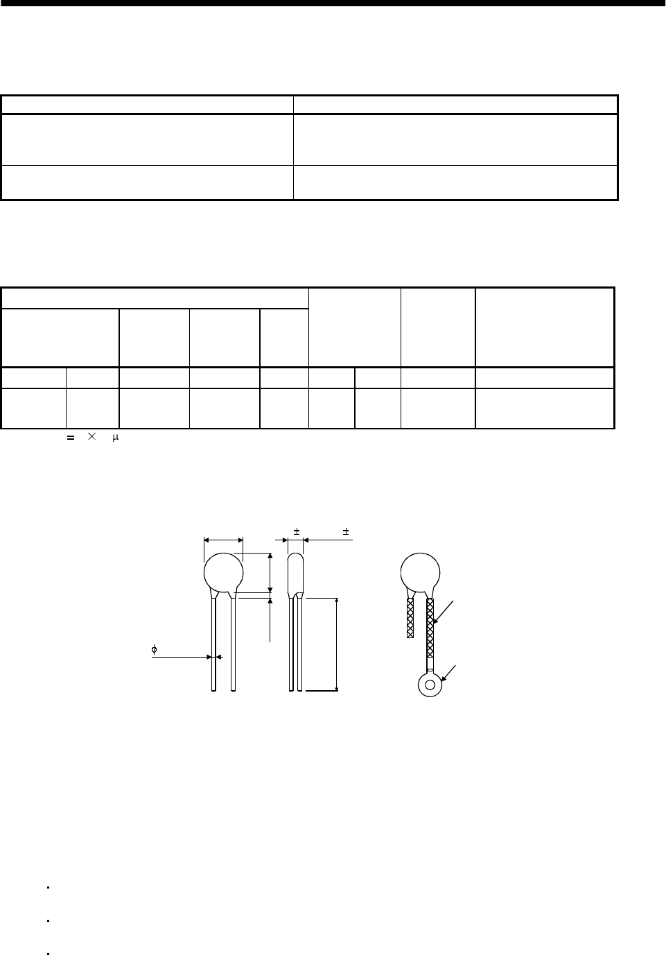
13.2.5 Surge absorbers
A surge absorber is required for the electromagnetic brake. Use the following surge absorber or equivalent.
Insulate the wiring as shown in the diagram.
Maximum rating
Permissible circuit
voltage
Surge
immunity
Energy
immunity
Rated
power
Maximum
limit voltage
Static
capacity
(reference
value)
Varistor voltage
rating (range) V1mA
AC[Vma] DC[V] [A] [J] [W] [A] [V] [pF] [V]
140 180
(Note)
500/time
5 0.4 25 360 300
220
(198 to 242)
Note: 1 time 8 20 s
(Example) ERZV10D221 (Matsushita Electric Industry)
TNR-10V221K (Nippon chemi-con)
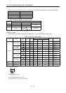
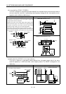
Outline drawing [mm] ( [in] ) (ERZ-C10DK221)
13.5 (0.53)
16.5
(0.65)
3.0 (0.12)
or less
30.0 (1.18)
or more
Crimping terminal
for M4 screw
Vinyl tube
4.7 1.0 (0.19 0.04)
0.8 (0.03)
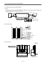
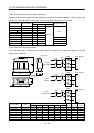
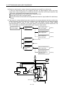
13.2.6 Noise reduction techniques
Noises are classified into external noises which enter the servo amplifier to cause it to malfunction and
those radiated by the servo amplifier to cause peripheral devices to malfunction. Since the servo amplifier
is an electronic device which handles small signals, the following general noise reduction techniques are
required.
Also, the servo amplifier can be a source of noise as its outputs are chopped by high carrier frequencies. If
peripheral devices malfunction due to noises produced by the servo amplifier, noise suppression measures
must be taken. The measures will vary slightly with the routes of noise transmission.
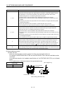
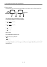
(1) Noise reduction techniques
(a) General reduction techniques
Avoid laying power lines (input and output cables) and signal cables side by side or do not bundle
them together. Separate power lines from signal cables.
Use shielded, twisted pair cables for connection with the encoder and for control signal
transmission, and connect the shield to the SD terminal.
Ground the servo amplifier, servo motor, etc. together at one point (refer to Section 3.10).