


7 - 4
7. GENERAL GAIN ADJUSTMENT
7.2.2 Auto tuning mode operation
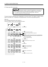
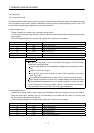
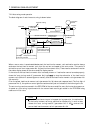
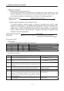
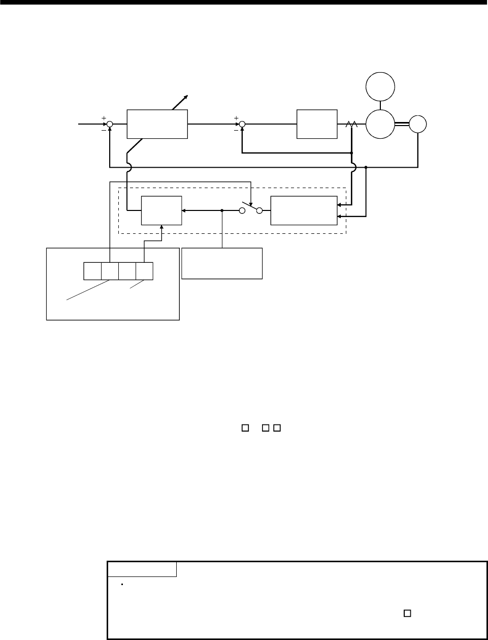
The block diagram of real-time auto tuning is shown below.
Servo
motor
7010
Command
Automatic setting
Control gains
PG1,VG1
PG2,VG2,VIC
Current
control
Current feedback
Load inertia
moment
Encoder
Position/speed
feedback
Real-time auto
tuning section
Speed feedback
Load inertia
moment ratio
estimation section
Gain
table
Parameter No. 2
Third digit
Auto tuning selection
First digit
Response level setting
Parameter No. 34
Load inertia moment
ratio estimation value
Set 0 or 1 to turn on.
Switch
When a servo motor is accelerated/decelerated, the load inertia moment ratio estimation section always
estimates the load inertia moment ratio from the current and speed of the servo motor. The results of
estimation are written to parameter No. 34 (load inertia moment ratio). These results can be confirmed on
the status display screen of the servo amplifier display section.
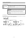
If the value of the load inertia moment ratio is already known or if estimation cannot be made properly,
chose the "auto tuning mode 2" (parameter No.2:
2 ) to stop the estimation of the load inertia
moment ratio (Switch in above diagram turned off), and set the load inertia moment ratio (parameter No.
34) manually.
From the preset load inertia moment ratio (parameter No. 34) value and response level (The first digit of
parameter No. 2), the optimum control gains are automatically set on the basis of the internal gain tale.
The auto tuning results are saved in the EEP-ROM of the servo amplifier every 6 minutes since power-on.
At power-on, auto tuning is performed with the value of each control gain saved in the EEP-ROM being
used as an initial value.
POINT
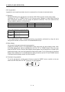
If sudden disturbance torque is imposed during operation, the estimation
of the inertia moment ratio may malfunction temporarily. In such a case,
choose the "auto tuning mode 2" (parameter No. 2: 020
) and set the
correct load inertia moment ratio in parameter No. 34.