


10 - 3
10. TROUBLESHOOTING
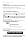
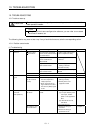
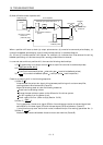
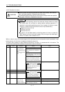
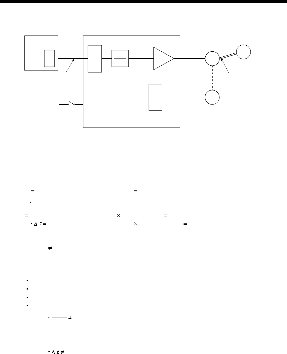
(2) How to find the cause of position shift
Positioning unit
(a) Output pulse
counter
Q
P
CMX
CDV
(C) Servo-on (SON),
stroke end
(LSP/LSN) input
(A)
(b) Cumulative command
pulses
Electronic gear (parameters No. 3, 4)
C
Servo motor
SM
Encoder
L
Machine
(d) Machine sto
p
position M
(B)
(c) Cumulative
feedback pulses
Servo amplifier
When a position shift occurs, check (a) output pulse counter, (b) cumulative command pulse display, (c)
cumulative feedback pulse display, and (d) machine stop position in the above diagram.
(A), (B) and (C) indicate position shift causes. For example, (A) indicates that noise entered the wiring
between positioning unit and servo amplifier, causing pulses to be mis-counted.
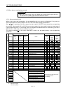
In a normal status without position shift, there are the following relationships:
1) Q
P (positioning unit's output counter servo amplifier's cumulative command pulses)
2)
CMX(parameter No.3)
CDV(parameter No.4)
P
C (cumulative command pulses electronic gear cumulative feedback pulses)
3) C
M (cumulative feedback pulses travel per pulse machine position)
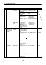
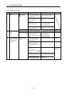
Check for a position shift in the following sequence:
1) When Q
P
Noise entered the pulse train signal wiring between positioning unit and servo amplifier,
causing pulses to be miss-counted. (Cause A)
Make the following check or take the following measures:
Check how the shielding is done.
Change the open collector system to the differential line driver system.
Run wiring away from the power circuit.
Install a data line filter. (Refer to (2)(a) Section 13.2.6.)
2)
CMX
CDV
P C
When
During operation, the servo-on signal (SON) or forward/reverse rotation stroke end signal was
switched off or the clear signal (CR) and the reset signal (RES) switched on. (Cause C)
If a malfunction may occur due to much noise, increase the input filter setting (parameter No. 1).
3) When C
M
Mechanical slip occurred between the servo motor and machine. (Cause B)