


15 - 38
15. ABSOLUTE POSITION DETECTION SYSTEM
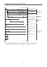
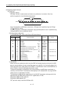
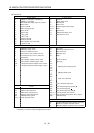
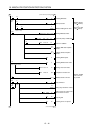
(b) Device list
X input contact Y output contact
X0 ABS bit 0 / completion of positioning Y0 Servo-on
X1 ABS bit 1 / zero speed Y1 ABS transfer mode
X2 Send ABS data ready/ torque limit control Y2 ABS request
X3 Servo alarm Y3 Alarm reset
X4 Alarm reset PB Y4
(Note 2)
Electromagnetic brake output
X5 Servo emergency stop Y5
(Note 1)
Clear
X6 Servo-on PB Y10 Servo alarm
X7 Servo ready Y11 ABS communication error
X10 JOG ( ) PB Y12 ABS check sum error
X11 JOG (−) PB
X12 Position start PB
X13 Position stop PB
X14 Home position return start PB
X15 1PG error reset
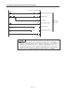
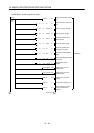
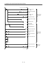
D register M contact
D0 ABS data: Lower 16 bits M0 Error flag
D1 ABS data: Upper 16 bits M1 ABS data transmission start
D2 Check sum addition counter M2 Retry command
D3 Check data in case of check sum error M3 ABS data read
D4 Transmission retry count in check sum
discrepancy
M4 Spare
D24 Home position address: Lower 16 bits M5 Servo-on request
D25 Home position address: Upper 16 bits M6 Retry flag
D106
D107
1PG present position address: Lower 16 bits
1PG present position address: Upper 16 bits
M10
M11
M12
M13
ABS data 2 bit receiving buffer
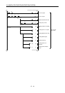
M20
M51
ABS data 32 bit buffer
M52
M57
Check sum 6 bit buffer
M58
M59
For checksum comparison
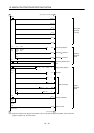
T timer M62 Sum check discrepancy (greater)
T200 Retry wait timer M63 Sum check discrepancy
T201 ABS transfer mode timer M64 Sum check discrepancy (less)
T202
T203
T204
T210
(Note 1)
ABS request response timer
Ready to send response timer
ABS data waiting timer
Clear signal ON timer
M70
(Note 1)
M71
(Note 1)
M99
Clear signal ON timer request
Data set type home position return request
ABS data ready
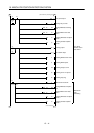
C counter
C0 All data reception frequency counter (19 times)
C1 Check sum reception frequency counter
C2 ABS data reception frequency counter (16 times)
Note 1: Necessary when data set type home position return is executed.
2: Necessary in the event of electromagnetic brake output.