


15 - 49
15. ABSOLUTE POSITION DETECTION SYSTEM
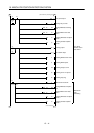
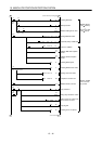
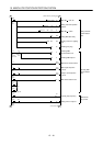
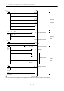
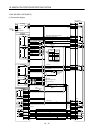
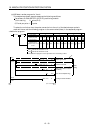
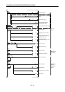
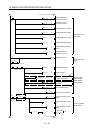
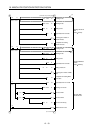
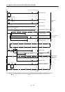
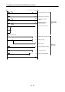
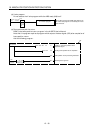
(2) Sequence program example
(a) Conditions
1) When the servo-on signal and power supply GND are shorted, the ABS data is transmitted at
power-on of the servo amplifier or on the leading edge of the RUN signal after a PC reset
operation (PC-RESET). The ABS data is also transmitted when an alarm is reset or when an
emergency stop is reset.
2) If a checksum mismatch is detected in the transmitted data, data transmission is retried up to
three times. If the checksum mismatch still persists after the retries, the ABS checksum error
occurs (Y3A ON).
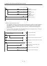
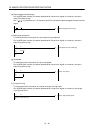
3) The following time periods are measured. If the ON/OFF state does not change within the
specified time, the ABS communication error occurs change within the specified time, the ABS
communication error occurs (Y3A ON):
ON period of ABS transfer mode (Y31)
ON period of ABS request (Y32)
OFF period of reading to send ABS data (X22)
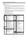
(b) Device list
X input contact Y output contact
X20 ABS bit 0 / positioning completion Y30 Servo-on
X21 ABS bit 1 / zero speed Y31 ABS transfer mode
X22 Reading to send ABS data / limiting torque Y32 ABS request
X23 Servo alarm Y33 Alarm reset
X24 Alarm reset X34
(Note 2)
Electromagnetic brake output
X25 Servo emergency stop Y35
(Note 1)
Clear
X26 Servo-on Y38 Servo alarm
X27 Home position return start Y39 ABS communication error
X28 Operation mode I Y3A ABS checksum error
X29 Operation mode II
D register M contact
D0 ABS data transmission counter M5 ABS data transmission start
D1 Checksum transmission counter M6 Sum check completion
D2 Checksum addition register M7 Sum check mismatch
D3 ABS data: Lower 16 bits M8 ABS data ready
D4 ABS data: Upper 16 bits M9 Transmission data read enabled
D5 ABS data 2-bit receiving buffer M10 Checksum 2 bits read completion
D6 Check data in case of checksum error M11 ABS 2 bits read completion
D7 Number of retries M12 ABS 2 bits request
D8 Forward rotation direction M13 Servo-on request
D9 Home position address: Lower 16 bits M14 Servo alarm
D10 Home position address: Upper 16 bits M15 ABS data transmission retry start pulse
D11 Drive unit ready data M16 Retry flag set
D12 Home position return completion data M17 Retry flag reset
D110 Received shift data: Lower 16 bits M18 PLS processing command
D111 Received shift data: Upper 16 bits M20
(Note 1)
Clear signal ON timer request
T timer M21
(Note 1)
Data set type home position return request
T0 ABS transmission mode timer
T1 ABS request response timer
M22 Home position return processing
instruction
T2 Retry wait timer
T3 ABS data send reading response timer
M23 Current position change processing
instruction
T10
(Note 1)
Clear signal ON timer M24 Current position change flag
T200 Transmitted data read 10ms delay timer C counter
C0 ABS data receive times counter
C1 Checksum receive times counter
C2 Retry counter
Note: 1.Required for data set type home position return.
2.Required for electromagnetic brake output.
3)
1)
2)
4)