


3 - 30
3. SIGNALS AND WIRING
3.4.3 Torque control mode
(1) Torque control
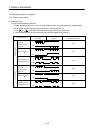
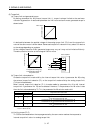
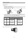
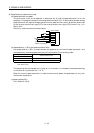
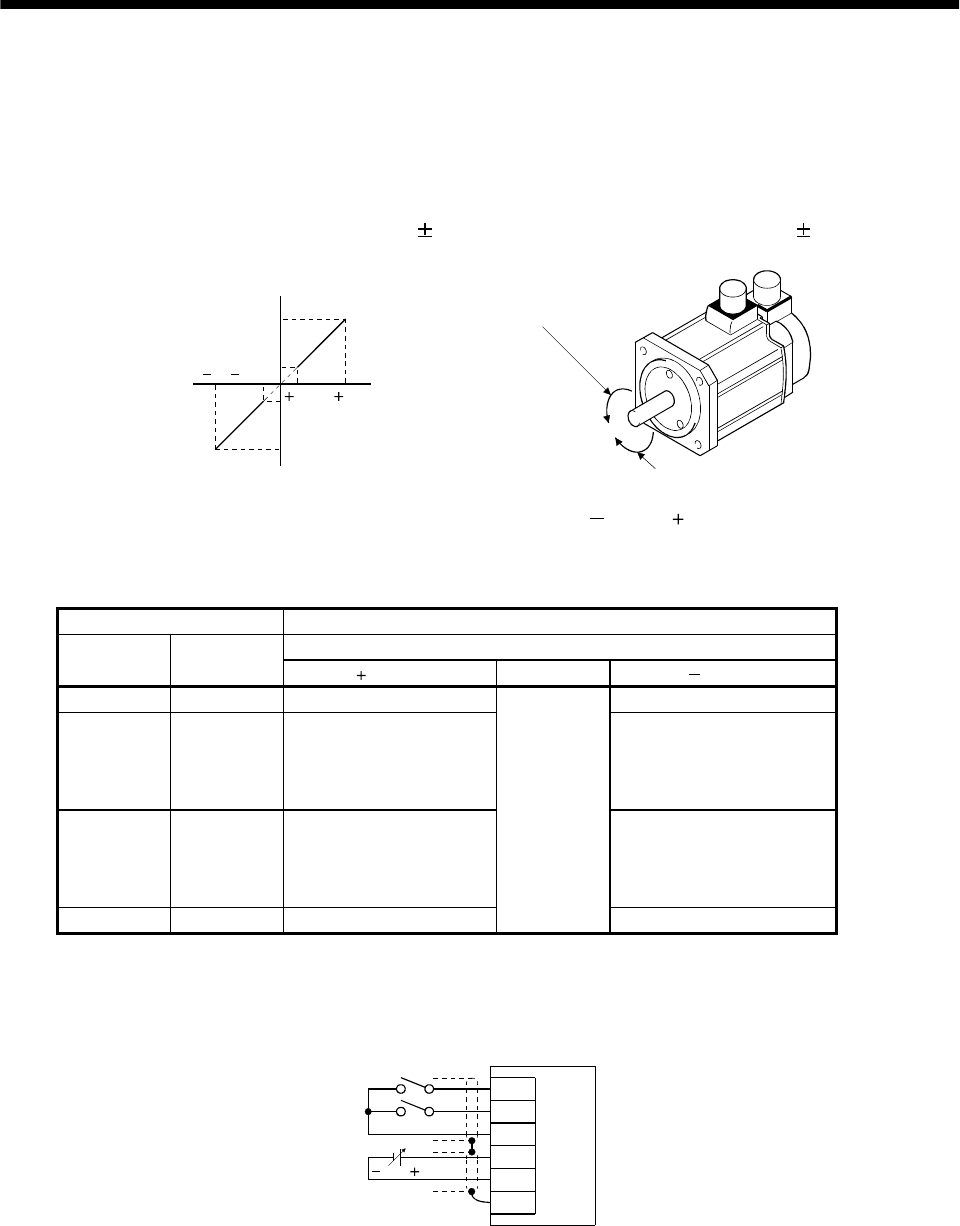
(a) Torque command and generated torque
A relationship between the applied voltage of the analog torque command (TC) and the torque
generated by the servo motor is shown below.
The maximum torque is generated at
8V. Note that the torque generated at 8V input can be
changed with parameter No. 26.
8
0.05 8
0.05
Max. torque
Generated torque
CCW direction
CW direction
Max. torque (Note)
TC applied voltage [V]
Forward rotation (CCW)
Reverse rotation (CW)
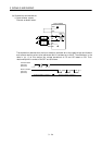
Generated torque limit values will vary about 5% relative to the voltage depending on products.
Also the generated torque may vary if the voltage is low (
0.05 to 0.05V) and the actual speed
is close to the limit value. In such a case, increase the speed limit value.
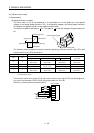
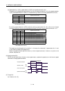
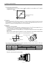
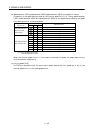
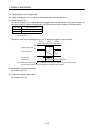
The following table indicates the torque generation directions determined by the forward rotation
selection (RS1) and reverse rotation selection (RS2) when the analog torque command (TC) is used.
(Note) External input signals Rotation direction
Torque control command (TC)
RS2 RS1
Polarity 0V Polarity
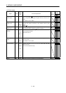
0 0 Torque is not generated. Torque is not generated.
01
CCW (reverse rotation in
driving mode/forward
rotation in regenerative
mode)
CW (forward rotation in
driving mode/reverse
rotation in regenerative
mode)
10
CW (forward rotation in
driving mode/reverse
rotation in regenerative
mode)
CCW (reverse rotation in
driving mode/forward
rotation in regenerative
mode)
1 1 Torque is not generated.
Torque is not
generated.
Torque is not generated.
Note. 0: RS1/RS2-SG off (open)
1: RS1/RS2-SG on (short)
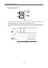
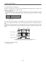
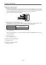
Generally, make connection as shown below:
RS1
RS2
SG
TC
LG
SD
8 to 8V
Servo amplifier