


3 - 28
3. SIGNALS AND WIRING
3.4.2 Speed control mode
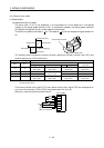
(1) Speed setting
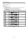
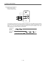
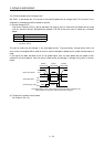
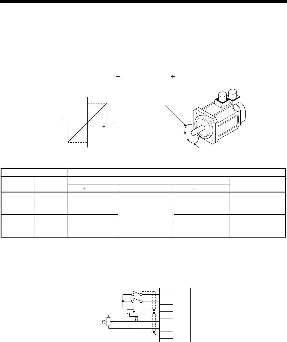
(a) Speed command and speed
The servo motor is run at the speeds set in the parameters or at the speed set in the applied
voltage of the analog speed command (VC). A relationship between the analog speed command
(VC) applied voltage and the servo motor speed is shown below:
The maximum speed is achieved at
10V. The speed at 10V can be changed using parameter No.
25.
10
010
Rated speed [r/min]
Speed [r/min]
CW direction
VC applied voltage [V]
CCW direction
Rated speed
Forward rotation (CCW)
Reverse rotation (CW)
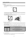
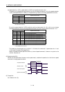
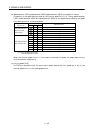
The following table indicates the rotation direction according to forward rotation start (ST1) and
reverse rotation start (ST2) combination:
(Note) External input signals Rotation direction
Analog speed command (VC)
ST2 ST1
Polarity 0V Polarity
Internal speed
commands
00
Stop
(Servo lock)
Stop
(Servo lock)
Stop
(Servo lock)
Stop
(Servo lock)
0 1 CCW CW CCW
10 CW
Stop
(No servo lock)
CCW CW
11
Stop
(Servo lock)
Stop
(Servo lock)
Stop
(Servo lock)
Stop
(Servo lock)
Note.0: ST1/ST2-SG off (open)
1: ST1/ST2-SG on (short)
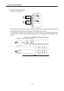
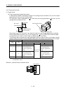
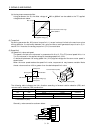
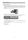
The forward rotation start signal (ST1) and reverse rotation start signal (ST2) can be assigned to
any pins of the connector CN1A, CN1B using parameters No. 43 to 48.
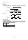
Generally, make connection as shown below:
ST1
ST2
SG
P15R
VC
LG
SD
2k
2k
Servo amplifier
Japan resistor
RRS10 or equivalent