


3 - 40
3. SIGNALS AND WIRING
3.6.2 Detailed description of the interfaces
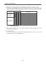
This section gives the details of the I/O signal interfaces (refer to I/O Division in the table) indicated in
Sections 3.3.2.
Refer to this section and connect the interfaces with the external equipment.
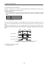
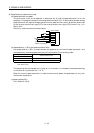
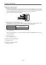
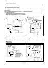
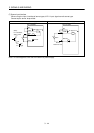
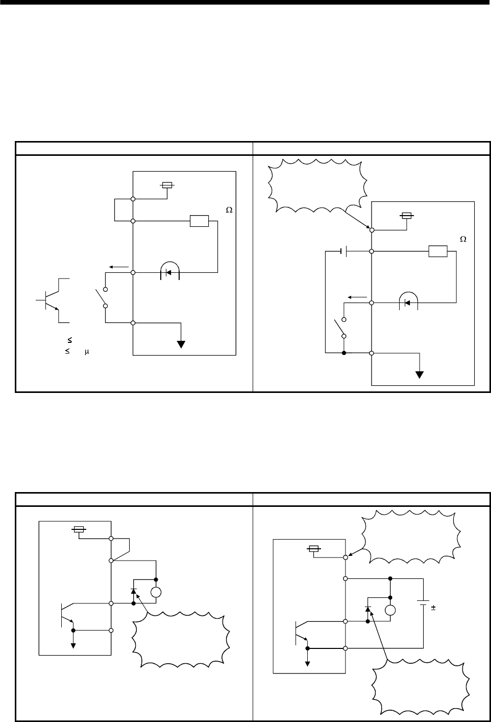
(1) Digital input interface DI-1
Give a signal with a relay or open collector transistor.
Source input is also possible. Refer to (7) in this section.
For use of internal power supply For use of external power supply
VDD
COM
24VDC
SGTR
Servo amplifier
R: Approx. 4.7
SON, etc.
(Note)
For a transistor
Approx. 5mA
V
CES
1.0V
I
CEO
100 A
Switch
COM
SG
Switch
SON, etc.
24VDC
200mA or more
Servo amplifier
R: Approx. 4.7
VDD
24VDC
Do not connect
VDD-COM.
Note: This also applies to the use of the external power supply.
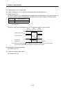
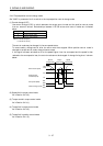
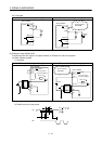
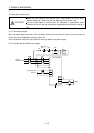
(2) Digital output interface DO-1
A lamp, relay or photocoupler can be driven. Provide a diode (D) for an inductive load, or an inrush
current suppressing resister (R) for a lamp load. (Permissible current: 40mA or less, inrush current:
100mA or less)
(a) Inductive load
For use of internal power supply For use of external power supply
VDD
24VDC
COM
SG
Servo amplifier
If the diode is not
connected as shown,
the servo amplifier
will be damaged.
Load
ALM, etc.
24VDC
10%
COM
SG
Servo amplifier
Load
ALM, etc.
If the diode is not
connected as shown,
the servo amplifier
will be damaged.
VDD
24VDC
Do not connect
VDD-COM.