


3 - 18
3. SIGNALS AND WIRING
Control
mode
Signal Symbol
Connec-
tor pin
No.
Functions/Applications
I/O
division
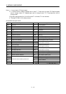
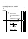
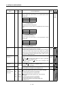
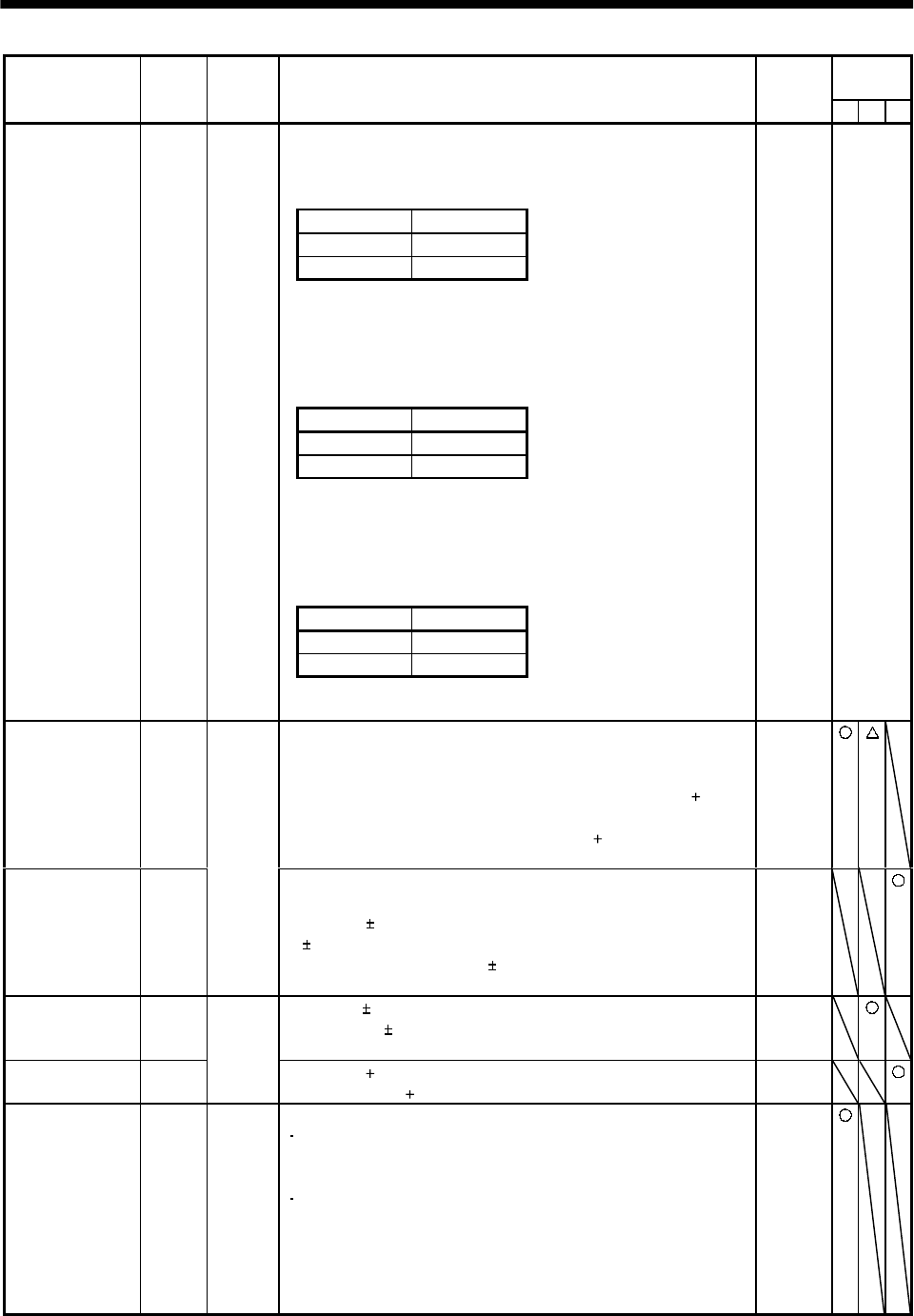
PST
<Position/speed control change mode>
Used to select the control mode in the position/speed control
change mode.
(Note) LOP Control mode
0Position
1 Speed
Note.0: LOP-SG off (open)
1: LOP-SG on (short)
<Speed/torque control change mode>
Used to select the control mode in the speed/torque control change
mode.
(Note) LOP Control mode
0 Speed
1Torque
Note.0: LOP-SG off (open)
1: LOP-SG on (short)
<Torque/position control mode>
Used to select the control mode in the torque/position control
change mode.
(Note) LOP Control mode
0Torque
1Position
Control change LOP CN1B
7
Note.0: LOP-SG off (open)
1: LOP-SG on (short)
DI-1
Refer to
Functions/
Appli-
cations.
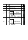
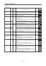
Analog torque
limit
TLA To use this signal in the speed control mode, set any of
parameters No. 43 to 48 to make TL available.
When the analog torque limit (TLA) is valid, torque is limited in
the full servo motor output torque range. Apply 0 to
10VDC
across TLA-LG. Connect the positive terminal of the power supply
to TLA. Maximum torque is generated at
10V. (Refer to (5) in
Section 3.4.1.) Resolution:10bit
Analog
input
Analog torque
command
TC
CN1B
12
Used to control torque in the full servo motor output torque
range.
Apply 0 to
8VDC across TC-LG. Maximum torque is generated
at
8V. (Refer to (1) in Section 3.4.3.)
The torque generated at
8V input can be changed using
parameter No. 26.
Analog
input
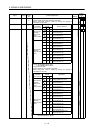
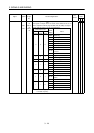
Analog speed
command
VC Apply 0 to 10VDC across VC-LG. Speed set in parameter No. 25
is provided at
10V. (Refer to (1) in Section 3.4.2.)
Resolution:14bit or equivalent
Analog
input
Analog speed
limit
VLA
CN1B
2
Apply 0 to
10VDC across VLA-LG. Speed set in parameter No.
25 is provided at
10V (Refer to (3) in Section 3.4.3.).
Analog
input
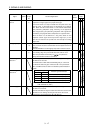
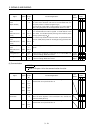
Forward rotation
pulse train
Reverse rotation
pulse train
PP
NP
PG
NG
CN1A
3
CN1A
2
CN1A
13
CN1A
12
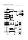
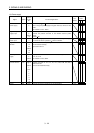
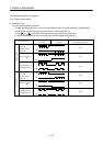
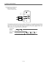
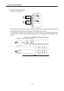
Used to enter a command pulse train.
In the open collector system (max. input frequency 200kpps):
Forward rotation pulse train across PP-SG
Reverse rotation pulse train across NP-SG
In the differential receiver system (max. input frequency
500kpps):
Forward rotation pulse train across PG-PP
Reverse rotation pulse train across NG-NP
The command pulse train form can be changed using
parameter No. 21.
DI-2