


3 - 13
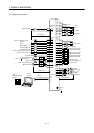
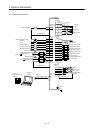
3. SIGNALS AND WIRING
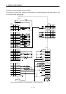
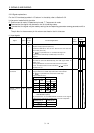
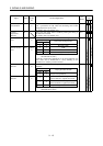
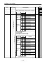
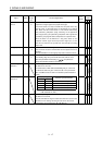
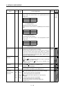
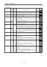
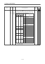
Note: 1. I : Input signal, O: Output signal
2. P : Position control mode, S: Speed control mode, T: Torque control mode, P/S: Position/speed
control change mode, S/T: Speed/torque control change mode, T/P: Torque/position control
change mode
3. By setting parameters No. 43 to 48 to make TL available, TLA can be used.
4. The signal of CN1A-18 is always output.
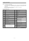
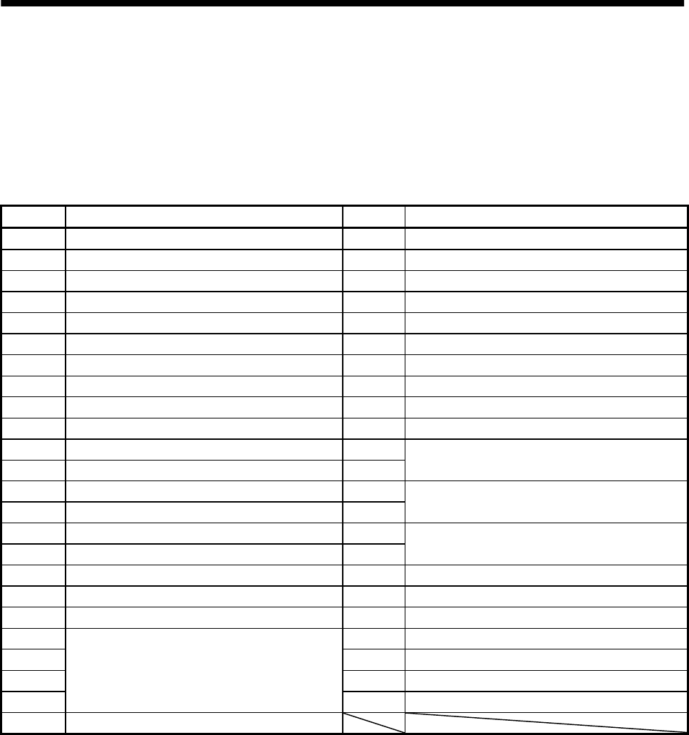
(3) Symbols and signal names
Symbol Signal name Symbol Signal name
SON Servo-on VLC Limiting speed
LSP Forward rotation stroke end RD Ready
LSN Reverse rotation stroke end ZSP Zero speed
CR Clear INP In position
SP1 Speed selection 1 SA Speed reached
SP2 Speed selection 2 ALM Trouble
PC Proportion control WNG Warning
ST1 Forward rotation start BWNG Battery warning
ST2 Reverse rotation start OP Encoder Z-phase pulse (open collector)
TL Torque limit selection MBR Electromagnetic brake interlock
RES Reset LZ
EMG Forced stop LZR
Encoder Z-phase pulse
(differential line driver)
LOP Control change LA
VC Analog speed command LAR
Encoder A-phase pulse
(differential line driver)
VLA Analog speed limit LB
TLA Analog torque limit LBR
Encoder B-phase pulse
(differential line driver)
TC Analog torque command VDD I/F internal power supply
RS1 Forward rotation selection COM Digital I/F power supply input
RS2 Reverse rotation selection OPC Open collector power input
PP SG Digital I/F common
NP P15R 15VDC power supply
PG LG Control common
NG
Forward/reverse rotation pulse train
SD Shield
TLC Limiting torque