


3
7. GENERAL GAIN ADJUSTMENT 7- 1 to 7-12
7.1 Different adjustment methods ............................................................................................................... 7- 1
7.1.1 Adjustment on a single servo amplifier.......................................................................................... 7- 1
7.1.2 Adjustment using servo configuration software............................................................................7- 2
7.2 Auto tuning .............................................................................................................................................. 7- 3
7.2.1 Auto tuning mode ............................................................................................................................. 7- 3
7.2.2 Auto tuning mode operation............................................................................................................ 7- 4
7.2.3 Adjustment procedure by auto tuning............................................................................................ 7- 5
7.2.4 Response level setting in auto tuning mode................................................................................... 7- 6
7.3 Manual mode 1 (simple manual adjustment)....................................................................................... 7- 7
7.3.1 Operation of manual mode 1 ........................................................................................................... 7- 7
7.3.2 Adjustment by manual mode 1 ....................................................................................................... 7- 7
7.4 Interpolation mode .................................................................................................................................7-10
7.5 Differences in auto tuning between MELSERVO-J2 and MELSERVO-J2-Super .......................... 7-11
7.5.1 Response level setting .....................................................................................................................7-11
7.5.2 Auto tuning selection....................................................................................................................... 7-11
8. SPECIAL ADJUSTMENT FUNCTIONS 8- 1 to 8-10
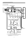
8.1 Function block diagram ..........................................................................................................................8- 1
8.2 Machine resonance suppression filter ................................................................................................... 8- 1
8.3 Adaptive vibration suppression control................................................................................................. 8- 3
8.4 Low-pass filter ......................................................................................................................................... 8- 4
8.5 Gain changing function........................................................................................................................... 8- 5
8.5.1 Applications....................................................................................................................................... 8- 5
8.5.2 Function block diagram.................................................................................................................... 8- 5
8.5.3 Parameters ........................................................................................................................................ 8- 6
8.5.4 Gain changing operation.................................................................................................................. 8- 8
9. INSPECTION 9- 1 to 9- 2
10. TROUBLESHOOTING 10- 1 to 10-12
10.1 Trouble at start-up ..............................................................................................................................10- 1
10.1.1 Position control mode ...................................................................................................................10- 1
10.1.2 Speed control mode.......................................................................................................................10- 4
10.1.3 Torque control mode.....................................................................................................................10- 5
10.2 When alarm or warning has occurred...............................................................................................10- 6
10.2.1 Alarms and warning list ..............................................................................................................10- 6
10.2.2 Remedies for alarms.....................................................................................................................10- 7
10.2.3 Remedies for warnings................................................................................................................10-12
11. OUTLINE DIMENSION DRAWINGS 11- 1 to 11- 8
11.1 Servo amplifiers...................................................................................................................................11- 1
11.2 Connectors............................................................................................................................................11- 6