


15 - 25
15. ABSOLUTE POSITION DETECTION SYSTEM
(3) Sequence program example
(a) Conditions
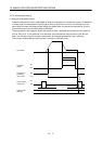
This sample program is an ABS sequence program example for a single axis (X axis).
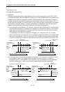
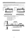
To transmit the ABS data using the OFF-to-ON change of the servo-on signal as the trigger.
1) When the servo-ON signal and the GND of the power supply are shorted, the ABS data is
transmitted when the power to the servo amplifier power is turned ON, or at the leading edge of
the RUN signal after a PC reset operation (PC-RESET). The ABS data is also transmitted when
an alarm is reset, or when the emergency stop state is reset.
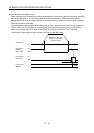
2) If a check sum discrepancy is detected in the transmitted data, ABS data transmission is retried
up to three times. If the check sum discrepancy is still detected after retrying, the ABS check
sum error is generated (Y4A ON).
3) The following time periods are measured and if the ON/OFF state does not change within the
specified time, the ABS communication error is generated (Y4A ON).
ON period of ABS transfer mode (Y41)
ON period of ABS request (Y42)
OFF period of ready to send ABS data (X32).
4) If the relationship between the polarity (
) of the received ABS data and the setting value for
parameter No. 14 (rotating direction) of A1SD71 (AD71) involves negative coordinate values,
which cannot be handled by the A1SD71 (AD71), the ABS coordinate error is generated (Y4B
ON).
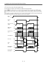
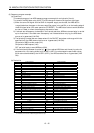
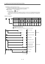
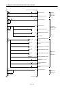
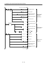
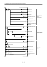
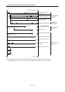
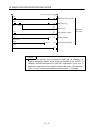
(b) Device list
X input contact Y output contact
X30 ABS bit 0 / completion of positioning Y40 Servo-on
X31 ABS bit 1 / zero speed Y41 ABS transfer mode
X32 Send ABS data ready / torque limit control Y42 ABS request
X33 Servo alarm Y43 Alarm reset
X34 Error reset X44
(Note 2)
Electromagnetic brake output
X35 Servo emergency stop Y45
(Note 1)
Clear
X36 Servo-on Y48 Servo alarm
X37 Home position return start Y49 ABS communication error
X38 Operation mode I Y4A ABS check sum error
X39 Operation mode II Y4B ABS coordinate error
D register M contact
D0 ABS data transmission counter M0 ABS data transmission start
D1 Check sum transmission counter M1 Sum check completion
D2 Check sum addition counter M2 Sum check discrepancy
D3 ABS data: Lower 16 bits M3 ABS data ready
D4 ABS data: Upper 16 bits M4 Transmission data read enabled
D5 ABS data 2-bit receiving buffer M5 Check sum 2 bits read completion
D6 Check data in case of check sum error M6 ABS 2 bits read completion
D7 Retry frequency M7 ABS 2 bits request
D8 Forward rotation direction M8 Servo-on request
D9 Home position address: Lower 16 bits M9 Servo alarm
D10 Home position address: Upper 16 bits M10 ABS data transmission retry start pulse
D100 Received shift data: Lower 16 bits M11 Retry flag setting
D101 Received shift data: Upper 16 bits M12 Retry flag reset
T timer M13 PLS processing command
T0 ABS transfer mode timer M20
(Note 1)
Clear signal ON timer request
T1 ABS request response timer M21
(Note 2)
Data set type home position return request
T2 Retry wait timer C counter
T3 Ready to send response timer C0 ABS data receive frequency counter
T10
(Note 1)
Clear signal ON timer C1 Check sum receive frequency counter
T200 Transmitted data read 10ms delay timer C2 Retry counter
Note 1: Necessary when data set type home position return is executed.
2: Necessary in the event of electromagnetic brake output.