


15 - 37
15. ABSOLUTE POSITION DETECTION SYSTEM
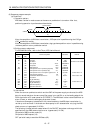
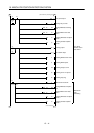
(2) Sequence program example
(a) Conditions
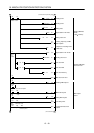
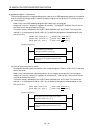
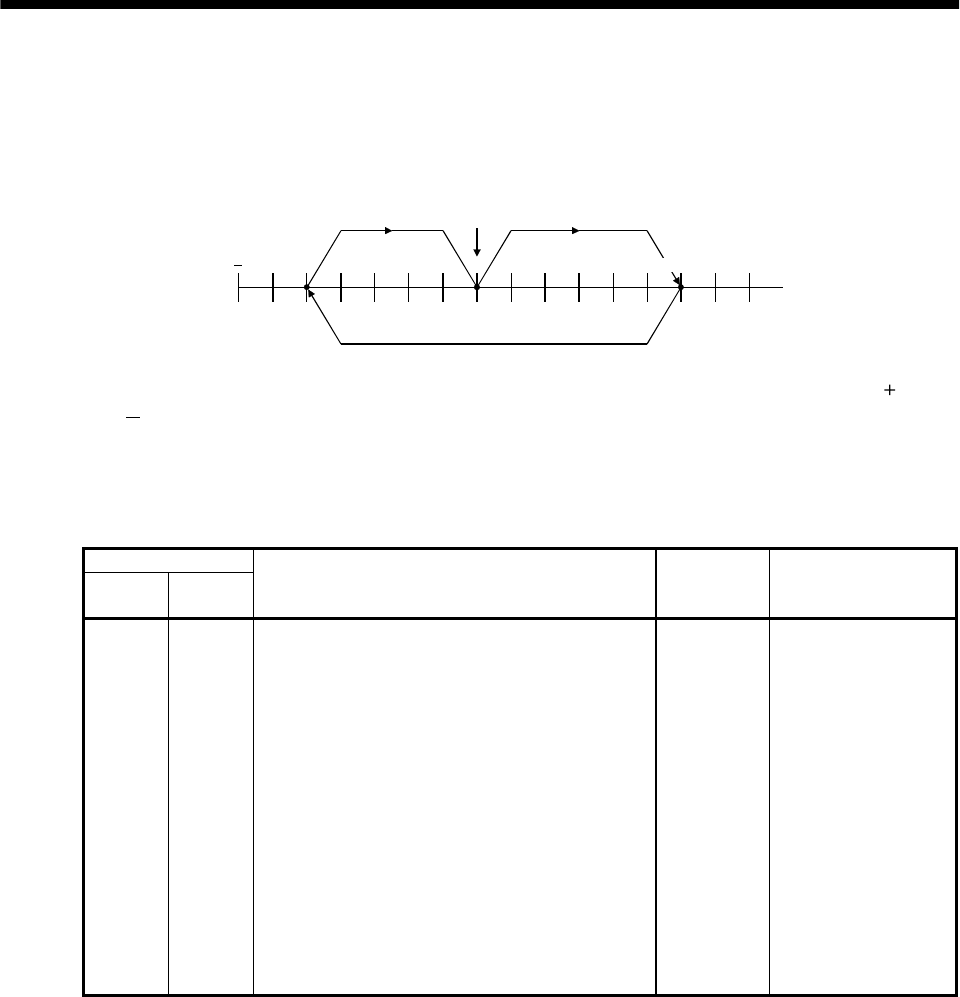
1) Operation pattern
ABS data transfer is made as soon as the servo-on pushbutton is turned on. After that,
positioning operation is performed as shown below:
300000 0
address
3) 1)
2)
Home position
300000
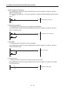
After the completion of ABS data transmission, JOG operation is possible using the JOG or
JOG
pushbutton switch.
After the completion of ABS data transmission, dog type home position return is possible using
the home position return pushbutton switch.
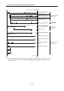
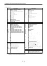
2) Buffer memory assignment
For BFM#26 and later, refer to the FX
2(N)
-1PG User's Manual.
BMF No.
Upper 16
bits
Lower 16
bits
Name and symbol Set value Remark
-
#0 Pulse rate A 2000
#2 #1 Feed rate B 1000
- #3 Parameter H0000 Command unit: Pulses
#5 #4 Max. speed Vmax 100000PPS
- #6 Bias speed Vbia 0PPS
#8 #7 JOG operation Vjog 10000PPS
#10 #9 Home position return speed (high speed) V
RT
50000PPS
- #11 Home position return speed (creep) V
CL
1000PPS
- #12 Home position return zero-point signal count N 2 pulses Initial value: 10
#14 #13 Home position address HP 0
- #15 Acceleration/deceleration time Ta 200ms Initial value: 100
- #16 Not usable
#18 #17 Target address (I) P(I) 0
#20 #19 Operation speed (I) V(I) 100000 Initial value: 10
#22 #21 Target address (II) P(II) 0
#24 #23 Operation speed (II) V(II) 10
- #25 Operation command H0000
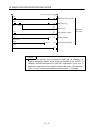
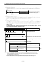
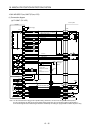
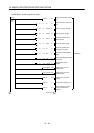
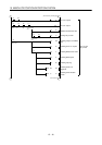
3) Instructions
When the servo-on pushbutton switch and the GND of the power supply are shorted, the ABS
data is transmitted when the servo amplifier power is turned ON, or at the leading edge of the
RUN signal after a PC reset operation (PC-RESET). The ABS data is also transmitted when an
alarm is reset, or when the emergency stop state is reset.
If check sum discrepancy is detected in the transmitted data, the ABS data transmission is
retried up to three times. If the check sum discrepancy is still detected after retrying, the ABS
check sum error is generated (Y12 ON).
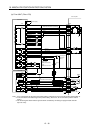
The following time periods are measured and if the ON/OFF state does not change within the
specified time, the ABS communication error is generated (Y11 ON).
ON period of ABS transfer mode (Y1)
ON period of ABS request (Y2)
OFF period of ready to send the ABS data (X2).