


3 - 5
3. SIGNALS AND WIRING
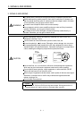
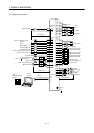
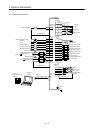
Note: 1. To prevent an electric shock, always connect the protective earth (PE) terminal (terminal
marked ) of the servo amplifier to the protective earth (PE) of the control box.
2. Connect the diode in the correct direction. If it is connected reversely, the servo amplifier will
be faulty and will not output signals, disabling the emergency stop and other protective
circuits.
3. The emergency stop switch (normally closed contact) must be installed.
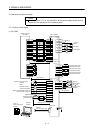
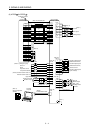
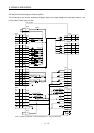
4. CN1A, CN1B, CN2 and CN3 have the same shape. Wrong connection of the connectors will
lead to a fault.
5. The sum of currents that flow in the external relays should be 80mA max. If it exceeds 80mA,
supply interface power from external.(Refer to Section 3.6.2)
6. When starting operation, always connect the emergency stop signal (EMG) and forward/
reverse rotation stroke end signal (LSN/LSP) with SG. (Normally closed contacts)
7. Trouble (ALM) is connected with COM in normal alarm-free condition. When this signal is
switched off (at occurrence of an alarm), the output of the controller should be stopped by the
sequence program.
8. When connecting the personal computer together with monitor outputs 1, 2, use the
maintenance junction card (MR-J2CN3TM). (Refer to Section 13.1.4)
9. The pins with the same signal name are connected in the servo amplifier.
10. This length applies to the command pulse train input in the differential line driver system.
It is 2m (6.5ft) or less in the opencollector system.
11. Use MRZJW3-SETUP 121E.
12. When using the internal power supply (VDD), always connect VDD-COM. Do not connect
them when supplying external power. Refer to Section 3.6.2.
13. Connect LG and pulse output COM to increase noise immunity.