


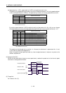
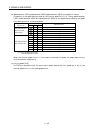
3 - 25
3. SIGNALS AND WIRING
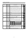
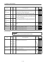
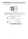
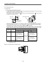
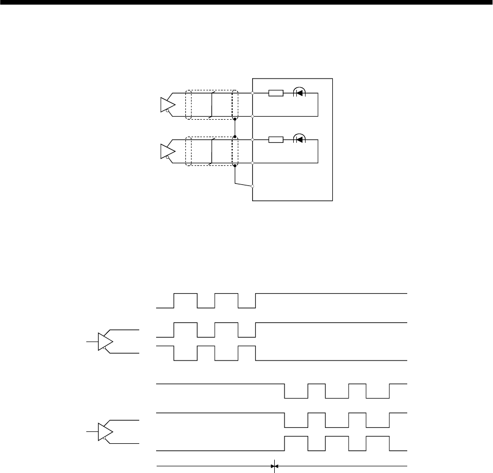
2) Differential line driver system
Connect as shown below:
PP
NP
Servo amplifier
PG
NG
SD
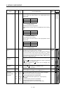
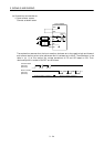
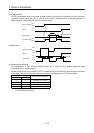
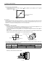
The explanation assumes that the input waveform has been set to the negative logic and forward
and reverse rotation pulse trains (parameter No.21 has been set to 0010).
For the differential line driver, the waveforms in the table in (a), (1) of this section are as follows.
The waveforms of PP, PG, NP and NG are based on that of the ground of the differential line
driver.
PP
PG
NP
NG
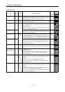
Forward rotation
pulse train
Reverse rotation
pulse train
Forward rotation command Reverse rotation command