


15 - 23
15. ABSOLUTE POSITION DETECTION SYSTEM
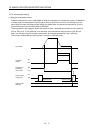
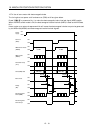
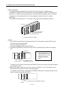
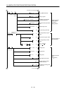
(d) Slot arrangement
The sequence programs presented in this section show I/O numbers (X, Y) assuming the
arrangement of modules on the main base unit is as illustrated below. A1SD71 is mounted at I/O
slots 0 and 1, a 16-point input module at slot 2, and 16-point output module at slot 3. If the actual
arrangement of the modules differs from this arrangement, change the X and Y numbers
accordingly.
The numbers of the devices (M, D, T, etc.) used in the program can be changed as required.
A1S
CPU
0
7
1
2
3
4
5
6
A1SD71
I/O slot No.
Example arran
g
ement of modules
[Numbers used] X, X0-X, Y2F
16-point input module
16-point output module
Power
supply
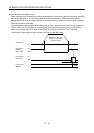
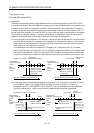
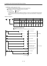
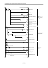
(e) Points
1) The A1SD71 has 48 I/O points and occupies 2 slots. For I/O allocation using the GPP function,
follow the instructions given below.
First slot: Vacant slot 16 points
Second slot: Special function module 32 points
2) To execute the FROM/TO instruction for the A1SD71, use the head I/O number of the second
slot.
A1S
CPU
A1SD71
X,Y000
to
X,Y00F
X,Y010
to
X,Y02F
X30 to X3F
Y40 to Y4F
I/O numbers to be set
with FROM/TO instruction
16-point input
module
16-point output
module
Note: The program example given
in (3) in this section is for 1-axis
control. Slot allocations are as
illustrated to the left. To use the
system for 2-axis control,
increase the number of I/O
points.
Therefore, the I/O number to be set with the FROM/TO instruction is head I/O number allocated
to the A1SD71
010
H
.
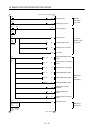
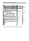
3) By setting "0 point of vacant slot" for the first slot of the A1SD71 in the "I/O allocation" of the
GPP function, the 16 points in the first slot can be saved.
In this case, the I/O number to be set with the FROM/TO instruction is the same number as the
head I/O number allocated to the A1SD71.
A1S
CPU
A1SD71
X,Y000
to
X,Y00F
I/O numbers to be set with FROM/TO instruction