


6 - 9
6. DISPLAY AND OPERATION
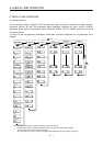
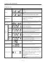
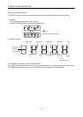
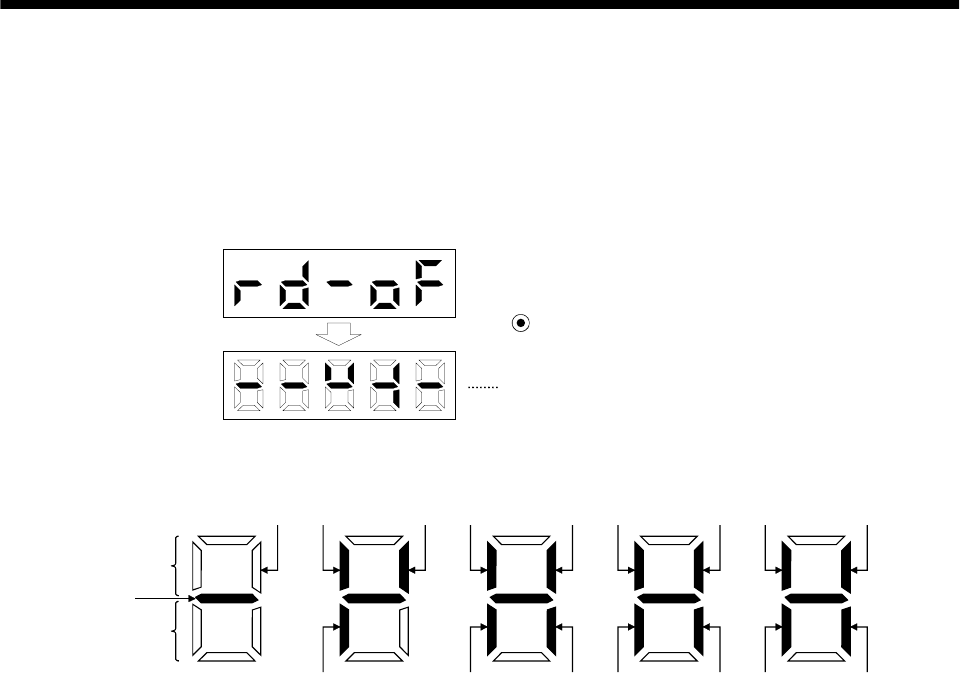
6.6 External I/O signal display
The ON/OFF states of the digital I/O signals connected to the servo amplifier can be confirmed.
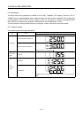
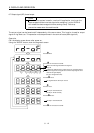
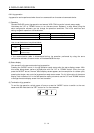
(1) Operation
Call the display screen shown after power-on.
Using the "MODE" button, show the diagnostic screen.
Press UP once.
External I/O signal display screen
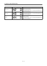
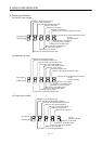
(2) Display definition
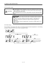
CN1B
7
CN1B
9
CN1B
8
CN1A
14
CN1A
8
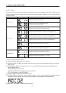
CN1B
4
CN1B
18
CN1B
14
CN1B
5
CN1B
17
CN1B
16
CN1B
19
CN1B
6
CN1A
19
CN1A
18
Lit: ON
Extinguished: OFF
Input signals
Output signals
CN1B
15
A
lways lit
The 7-segment LED shown above indicates ON/OFF.
Each segment at top indicates the input signal and each segment at bottom indicates the output signal.
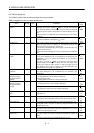
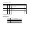
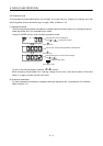
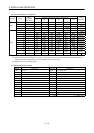
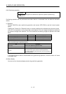
The signals corresponding to the pins in the respective control modes are indicated below: