


12 - 5
12. CHARACTERISTICS
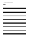
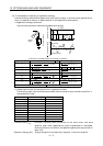
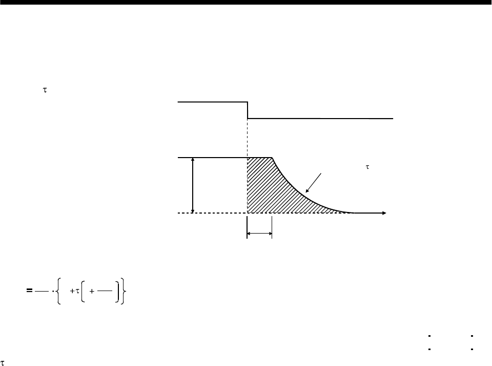
12.3 Dynamic brake characteristics
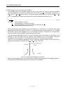
Fig. 12.4 shows the pattern in which the servo motor comes to a stop when the dynamic brake is operated.
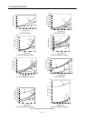
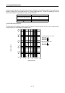
Use Equation 12.2 to calculate an approximate coasting distance to a stop. The dynamic brake time
constant
varies with the servo motor and machine operation speeds. (Refer to Fig. 12.5)
V
0
Time constant
Emergency stop(EMG)
OFF
ON
Machine speed
t
e
Time
Fig. 12.5 Dynamic brake operation diagram
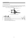
L
max
60
V
0
J
L
J
M
t
e
1
....................................................................................................................... (12.2)
L
max
: Maximum coasting distance .................................................................................................[mm][in]
Vo : Machine rapid feedrate ......................................................................................... [mm/min][in/min]
J
M
: Servo motor inertial moment.................................................................................[kg cm
2
][oz in
2
]
J
L
: Load inertia moment converted into equivalent value on servo motor shaft.....[kg cm
2
][oz in
2
]
: Brake time constant (Fig. 12.5)......................................................................................................[s]
t
e
: Delay time of control section (Fig. 12.4)......................................................................................... [s]
(There is internal relay delay time of about 30ms.)