13 - 4
13. OPTIONS AND AUXILIARY EQUIPMENT
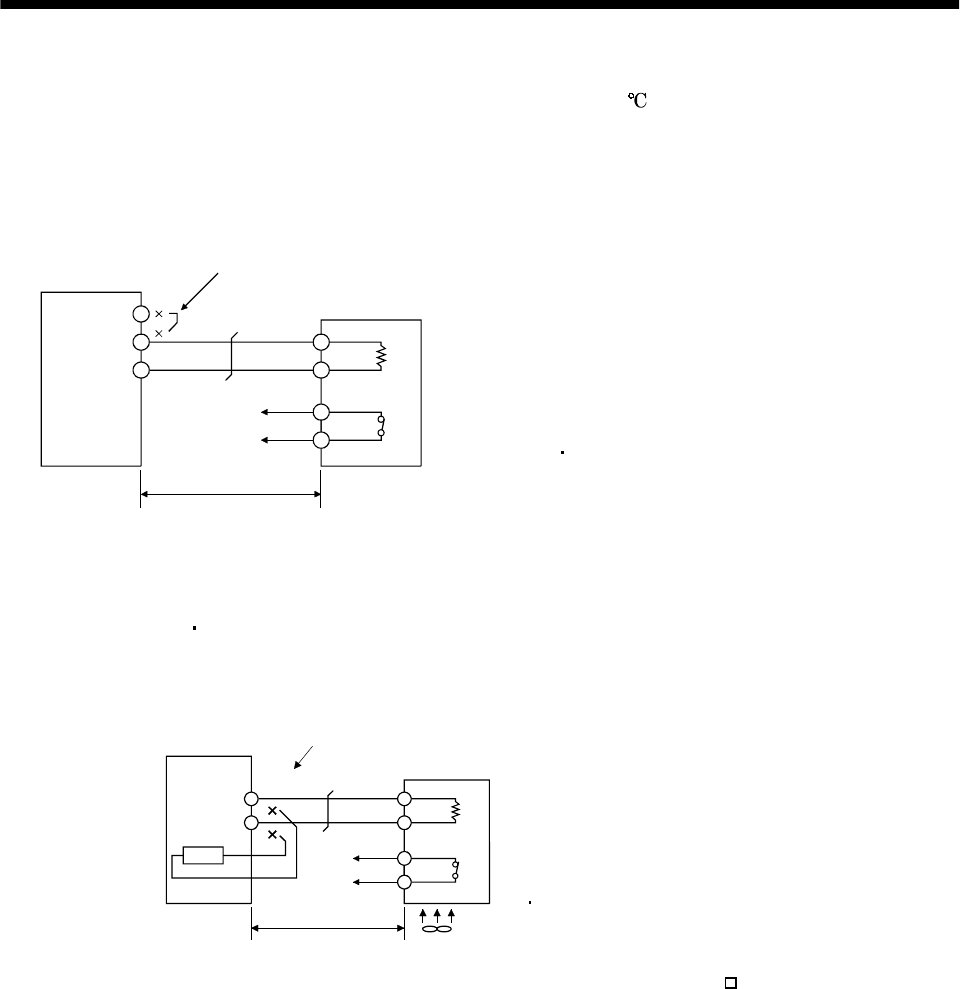
(4) Connection of the regenerative brake option
The regenerative brake option will generate heat of about 100
. Fully examine heat dissipation,
installation position, used cables, etc. before installing the option. For wiring, use flame-resistant
cables and keep them clear of the regenerative brake option body. Always use twisted cables of max.
5m(16.4ft) length for connection with the servo amplifier.
(a) MR-J2S-350A or less
Always remove the wiring from across P-D and fit the regenerative brake option across P-C.
Servo amplifier
Regenerative brake option
Note: Make up a sequence which will switch off the magnetic contactor
(MC) when abnormal heating occurs.
(Note)
5m (16.4 ft) max.
G3 G4: Thermal protector terminals.
Abnormal heating will dis-
connect G3-G4.
D
P
P
C
G3
G4
C
Always remove the lead from across P-D.
(b) MR-J2S-500A MR-J2S-700A
Always remove the wiring (across P-C) of the servo amplifier built-in regenerative brake resistor
and fit the regenerative brake option across P-C.
P
P
C
G3
(Note 2)
5m(16.4ft) or less
G4
C
Servo amplifier
Always remove wiring (across P-C) of servo
amplifier built-in regenerative brake resistor.
Regenerative brake option
G3 G4: Thermal protector terminals.
Abnormal heating will dis-
connect G3-G4.
Fan (Note 1)
Note 1. When using the MR-RB51, forcibly cool it with a cooling fan (1.0m
3
/min, 92 or so).
2. Make up a sequence which will switch off the magnetic contactor (MC)
when abnormal heating occurs.


