


4 - 2
4. OPERATION
4.2 Startup
WARNING
Do not operate the switches with wet hands. You may get an electric shock.
CAUTION
Before starting operation, check the parameters. Some machines may perform
unexpected operation.
During power-on for some after power-off, do not touch or close a parts (cable etc.)
to the servo amplifier heat sink, regenerative brake resistor, the servo motor, etc.
Their temperatures may be high and you may get burnt or a parts may damaged.
Connect the servo motor with a machine after confirming that the servo motor operates properly alone.
4.2.1 Selection of control mode
Use parameter No. 0 to choose the control mode used. After setting, this parameter is made valid by
switching power off, then on.
4.2.2 Position control mode
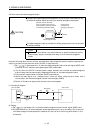
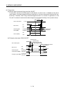
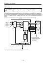
(1) Power on
1) Switch off the servo-on (SON) signal.
2) When main circuit power/control circuit power is switched on, the display shows "C (Cumulative
feedback pulses)", and in two second later, shows data.
In the absolute position detection system, first power-on results in the absolute position lost (AL.25)
alarm and the servo system cannot be switched on. This is not a failure and takes place due to the
uncharged capacitor in the encoder.
The alarm can be deactivated by keeping power on for a few minutes in the alarm status and then
switching power off once and on again.
Also in the absolute position detection system, if power is switched on at the servo motor speed of
500r/min or higher, position mismatch may occur due to external force or the like. Power must
therefore be switched on when the servo motor is at a stop.
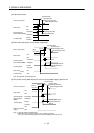
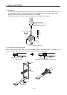
(2) Test operation 1
Using jog operation in the test operation mode, make sure that the servo motor operates. (Refer to
Section 6.8.2.)
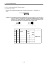
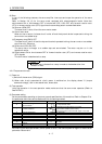
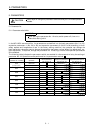
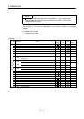
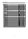
(3) Parameter setting
Set the parameters according to the structure and specifications of the machine. Refer to Chapter 5 for
the parameter definitions and to Sections 6.5 for the setting method.
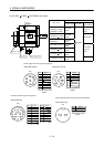
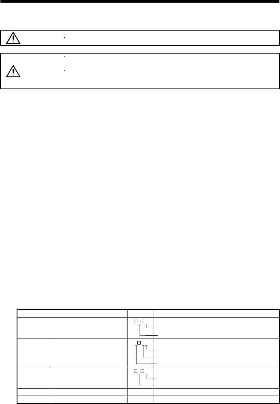
Parameter No. Name Setting Description
0
Control mode, regenerative brake
option selection
3 0
Position control mode
MR-RB12 regenerative brake option is used.
1 Function selection 1
0
0 2
Input filter 3.555ms (initial value)
Electromagnetic brake interlock signal is not used.
Used in incremental positioning system.
2 Auto tuning
1 5
Middle response (initial value) is selected.
Auto tuning mode 1 is selected.
3 Electronic gear numerator (CMX) 2 Electronic gear numerator
4 Electronic gear denominator (CDV) 1 Electronic gear denominator
After setting the above parameters, switch power off once. Then switch power on again to make
the set parameter values valid.