


7 - 10
7. GENERAL GAIN ADJUSTMENT
7.4 Interpolation mode
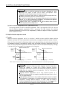
The interpolation mode is used to match the position control gains of the axes when performing the
interpolation operation of servo motors of two or more axes for an X-Y table or the like. In this mode, the
position control gain 2 and speed control gain 2 which determine command trackability are set manually
and the other parameter for gain adjustment are set automatically.
(1) Parameter
(a) Automatically adjusted parameters
The following parameters are automatically adjusted by auto tuning.
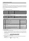
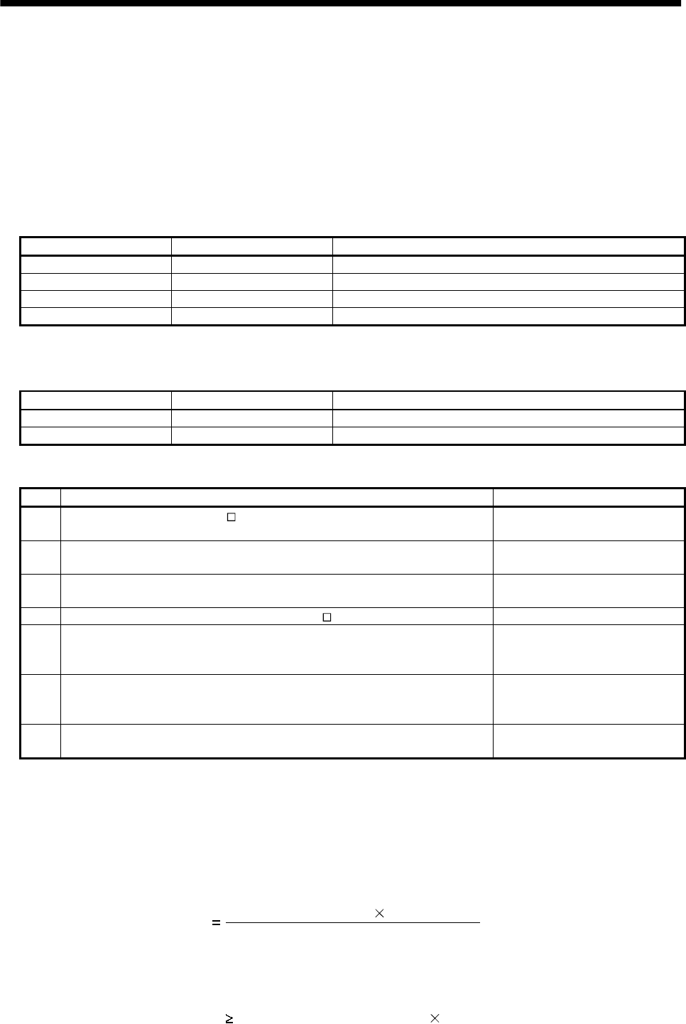
Parameter No. Abbreviation Name
34 GD2 Ratio of load inertia moment to servo motor inertia moment
35 PG2 Position control gain 2
37 VG2 Speed control gain 2
38 VIC Speed integral compensation
(b) Manually adjusted parameters
The following parameters are adjustable manually.
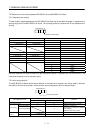
Parameter No. Abbreviation Name
6PG1Position control gain 1
36 VG1 Speed control gain 1
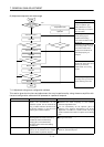
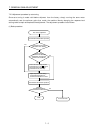
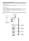
(2) Adjustment procedure
Step Operation Description
1
Set 15Hz (parameter No. 2: 010
) as the machine resonance frequency of response
in the auto tuning mode 1.
Select the auto tuning mode 1.
2
During operation, increase the response level setting (parameter No. 2), and
return the setting if vibration occurs.
Adjustment in auto tuning mode
1.
3
Check the values of position control gain 1 (parameter No. 6) and speed control
gain 1 (parameter No. 36).
Check the upper setting limits.
4 Set the interpolation mode (parameter No. 2: 000 ). Select the interpolation mode.
5
Using the position control gain 1 value checked in step 3 as the guideline of the
upper limit, set in PG1 the value identical to the position loop gain of the axis to
be interpolated.
Set position control gain 1.
6
Using the speed control gain 1 value checked in step 3 as the guideline of the
upper limit, look at the rotation status and set in speed control gain 1 the value
three or more times greater than the position control gain 1 setting.
Set speed control gain 1.
7
Looking at the interpolation characteristic and rotation status, fine-adjust the
gains and response level setting.
Fine adjustment.
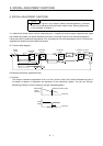
(3) Adjustment description
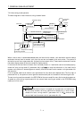
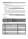
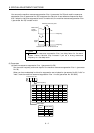
(a) Position control gain 1 (parameter No.6)
This parameter determines the response level of the position control loop. Increasing position
control gain 1 improves trackability to a position command but a too high value will make
overshooting liable to occur at the time of settling. The droop pulse value is determined by the
following expression.
Droop pulse value (pulse)
Position control gain 1 setting
Rotation speed (r/min) 131,072(pulse)
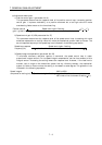
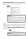
(b) Speed control gain 1 (parameter No. 36)
Set the response level of the speed loop of the model. Make setting using the following expression
as a guideline.
Speed control gain 1 setting
Position control gain 1 setting 3