


15 - 9
15. ABSOLUTE POSITION DETECTION SYSTEM
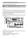
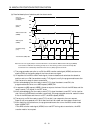
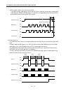
1) The ready signal (RD) is turned ON when the ABS transfer mode signal (ABSM) is turned OFF
after transmission of the ABS data.
While the ready signal (RD) is ON, the ABS transfer mode signal (ABSM) input is not accepted.
2) Even if the servo-on (SON) signal is turned ON before the ABS transfer mode signal (ABSM) is
turned ON, the base circuit is not turned ON until the ABS transfer mode signal (ABSM) is
turned ON.
If a servo alarm has occurred, the ABS transfer mode signal (ABSM) is not received.
The ABS transfer mode signal (ABSM) allows data transmission even while a servo warning is
occurring.
3) If the ABS transfer mode signal (ABSM) is turned OFF during the ABS transfer mode, the ABS
transfer mode is interrupted and the time-out error (AL.E5) occurs.
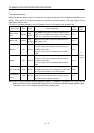
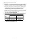
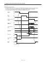
4) The functions of output signals such as ZSP, TLC, D01, and INP change depending on the
ON/OFF state of the ABS transfer mode signal (ABSM).
Note that if the ABS transfer mode signal (ABSM) is turned ON for a purpose other than ABS
data transmission, the output signals will be assigned the functions of ABS data transmission.
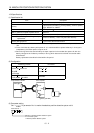
Output signal
Symbol Pin No.
ABS transfer mode (ABSM): OFF ABS transfer mode (ABSM): ON
(Note)
D01
CN1B-4 Positioning completion ABS data bit 0
ZSP CN1B-19 Zero speed ABS data bit 1
TLC CN1B-6 During torque limit control Send data ready
(Note)
INP
CN1A-18 Positioning completion ABS data bit 0
Note: CN1B-4 and CN1A-18 output the same signals. (To enter the positioning completion
signal into INPS of the AD75, connect CN1A-18.)