


15 - 35
15. ABSOLUTE POSITION DETECTION SYSTEM
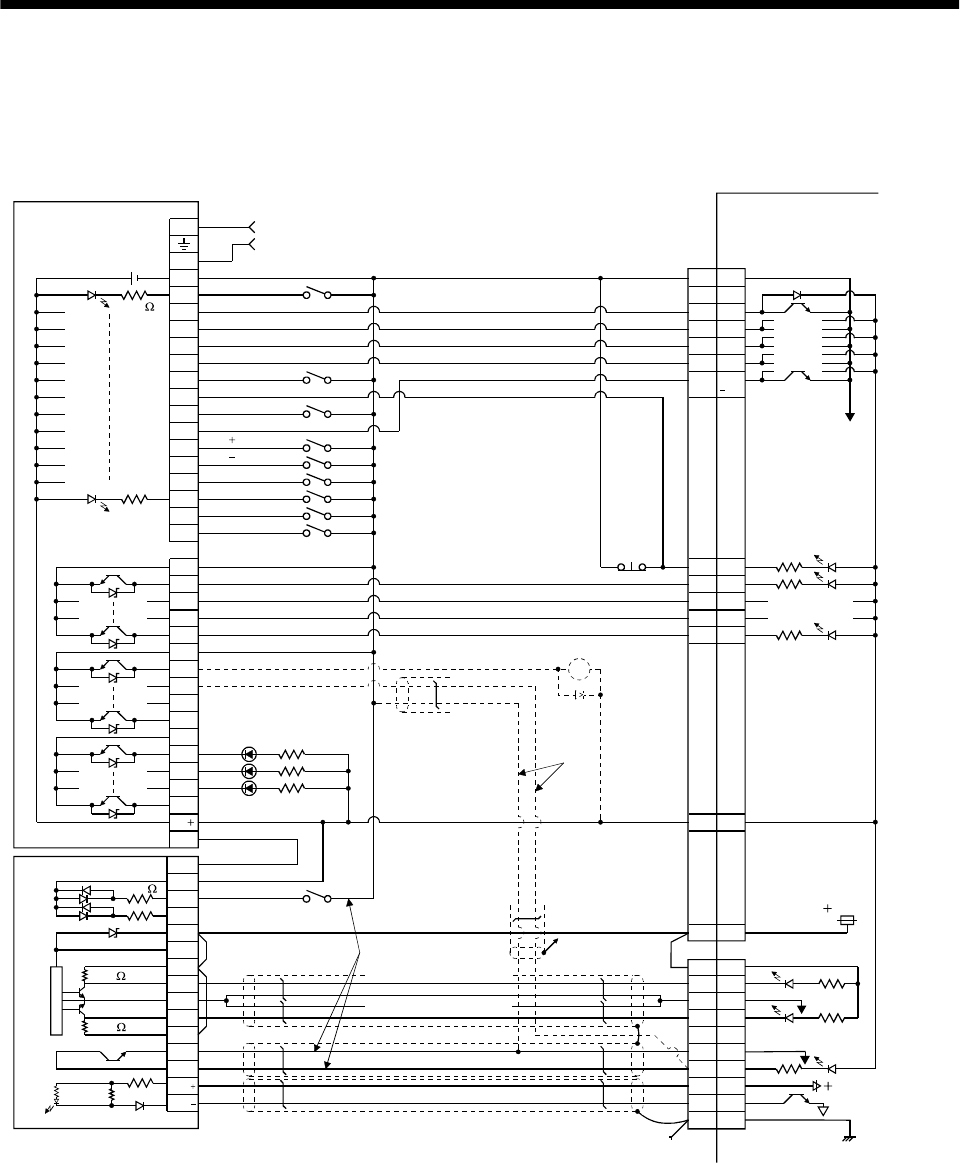
15.8.2 MELSEC FX
(2N)
-32MT (FX
(2N)
-1PG)
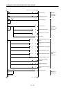
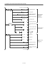
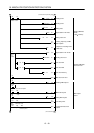
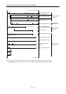
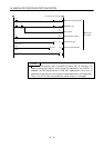
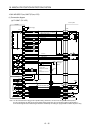
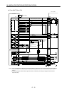
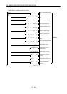
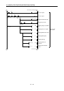
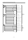
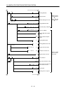
(1) Connection diagram
(a) FX-32MT (FX-1PG)
3.3k
3.3k
3.3k
N
COM2
Y4
Y5
Y6
Y10
24
SG
SG
S/S
DOG
STOP
VH
VL
FPO
FP
COM0
RP
RPO
COM1
CLR
L
Power supply
FX-32MT
SG 10
DO1 4
ZSP 19
TLC 6
ALM 18
RD
EMG 15
SON 5
ABSM
8
ABSR
9
RES 14
DOG
SD
15V
FX-1PG
Servo amplifier
COM
RUN
X1
X2
X3
X4
X5
X6
X7
X10
X11
X12
X13
X14
X15
COM1
Y0
X0
PC-RUN
Y1
Y2
Y3
Y7
COM3
Y11
Y12
Y13
RA2
COM
13
PGO
PGO
VDD 3
PP 3
SG 20
NP 2
SG 10
CR 8
P15R
4
OP 14
SD
Plate
24V
SD
3.3k
24V
CN1B
OPC
CN1A
11
ABS bit 0/Completion of positioning
ABS bit 1/Zero speed
Send data ready/Torque limit control
Alarm
Servo ready
JOG( )
JOG( )
Alarm reset
Servo-on
Position start
Position stop
Home position return start
1PG error reset
Emergency stop
CN1A
19
Servo-on
ABS transfer mode
ABS request
Alarm reset
Electromagnetic
brake output
(Note 3)
(Note 2)
Servo alarm
ABS communication
error
ABS check sum error
Pulse train for forward rotation
Pulse train for reverse rotation
Clear
Z-phase pulse
(Note 1)
Note 1: To be connected for the dog type home position setting. At this time, do not connect the portions marked (Note 2).
2: To be connected for the data set type home position setting. At this time, do not connect the portions marked (Note 1).
3: The electromagnetic brake interlock signal should be controlled by connecting the programmable controller output to a relay.