


3 - 47
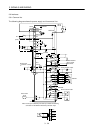
3. SIGNALS AND WIRING
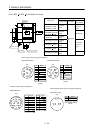
3.7.2 Terminals
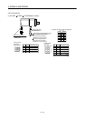
The positions and signal arrangements of the terminal blocks change with the capacity of the servo
amplifier. Refer to Section 11.1.
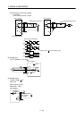
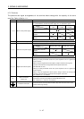
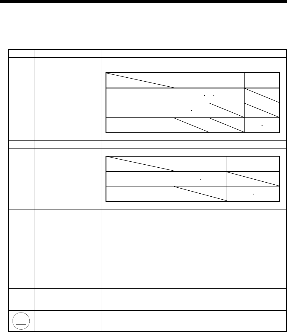
Symbol Signal Description
Supply L
1
, L
2
and L
3
with the following power:
For 1-phase 230VAC, connect the power supply to L
1
/L
2
and leave L
3
open.
Servo amplifier
Power supply
MR-J2S-10A to
70A
MR-J2S-100A
to 700A
MR-J2S-10A1
to 40A1
3-phase 200 to 230VAC,
50/60Hz
L
1
L
2
L
3
1-phase 230VAC,
50/60Hz
L
1
L
2
1-phase 100 to 120VAC,
50/60Hz
L
1
L
2
L
1
, L
2
, L
3
Main circuit power supply
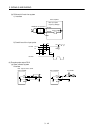
U, V, W Servo motor output Connect to the servo motor power supply terminals (U, V, W).
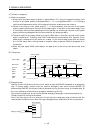
Servo amplifier
Power supply
MR-J2S-10A to 700A MR-J2S-10A1 to 40A1
1-phase 200 to 230VAC,
50/60Hz
L
11
L
21
1-phase 100 to 120VAC,
50/60Hz
L
11
L
21
L
11
, L
21
Control circuit power supply
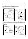
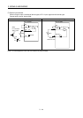
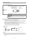
P, C, D Regenerative brake option
1) MR-J2S-350A or less
Wiring is factory-connected across P-D (servo amplifier built-in regenerative
brake resistor).
When using the regenerative brake option, always remove the wiring from
across P-D and connect the regenerative brake option across P-C.
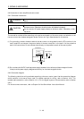
2) MR-J2S-500A or more
Wiring is factory-connected across P-C (servo amplifier built-in regenerative
brake resistor).
When using the regenerative brake option, always remove the wiring from
across P-C and connect the regenerative brake option across P-C.
Refer to Section 13.1.1 for details.
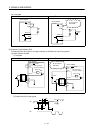
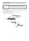
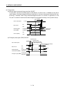
N
Return converter
Brake unit
When using the return converter or brake unit, connect it across P-N.
Do not connect it to the servo amplifier of MR-J2S-350A or less.
Refer to Sections 13.1.2 and 13.1.3 for details.
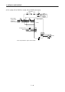
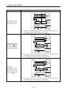
Protective earth (PE)
Connect this terminal to the protective earth (PE) terminals of the servo motor
and control box for grounding.