


13 - 7
13. OPTIONS AND AUXILIARY EQUIPMENT
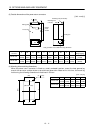
13.1.2 Brake unit
POINT
The brake unit and resistor unit of other than 200V class are not
applicable to the servo amplifier.
The brake unit and resistor unit of the same capacity must be combined.
The units of different capacities may result in damage.
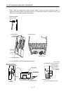
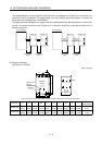
The brake unit and resistor unit must be installed on a vertical surface in
the vertical direction. If they are installed in the horizontal direction or on
a horizontal surface, a heat dissipation effect reduces.
The temperature of the resistor unit casing rises to higher than 100 . Do
not cause cables and combustibles to make contact with the casing.
The brake unit is the integration of the regenerative control and resistor and is connected to the bus
(across P-N) of the servo amplifier. As compared to the MR-RB regenerative brake option, the brake unit
can return larger power. Hence, use the this brake unit when the MR-RB cannot provide sufficient
regenerative brake capability.
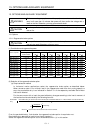
(1) Selection
Brake unit Resistor unit
Permissible Continuous
Power [kw]
Max. Instantaneous
Current [kw]
Applicable Servo Amplifier
FR-BU-15K FR-BR-15K 0.99 16.5
FR-BU-30K FR-BR-30K 1.99 33.4
MR-J2S-500A
MR-J2S-700A
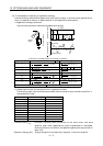
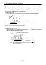
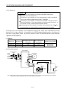
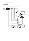
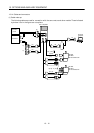
(2) Connection example
Servo motor
Servo amplifier
FR-BR resistor unit
SM
MC
NFB
L
1
L
2
L
3
L
11
L
21
U
V
W
(Note 2)
P
C
N
P/
N/
PR
HA
HB
HC
Alarm
output
PR
P
TH1
TH2
THS
Power
supply
3-phase
200 to
230VAC
No-fuse breaker
(Note 1)
(Note 1)
FR-BU brake unit
Note 1. Make up the external sequence to switch the power off when an alarm occurs or when the thermal relay is actuated.
2. Always remove the wiring (across P-C) of the servo amplifier built-in resistor.