


1 - 2
1. FUNCTIONS AND CONFIGURATION
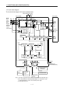
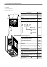
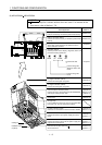
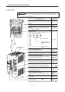
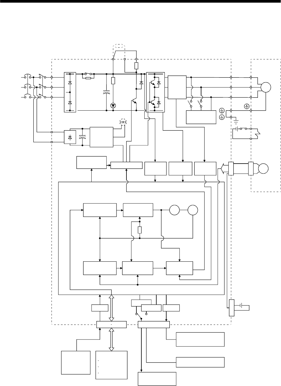
1.2 Function block diagram
The function block diagram of this servo is shown below.
Regenerative
brake
Base amplifier
Voltage
detection
Overcurrent
protection
Encoder
Dynamic
brake
Current
detector
CHARGE
lamp
RADS
Control
power
supply
(MR-J2S-200A or more)
Fan
Electro-
magnetic
brake
Servo motor
D
C
P
Regenerative brake option
NFB
Power
supply
3-phase
200 to
230VAC,
1-phase
230VACor
1-phase
100to120VAC
MC
L
1
L
2
L
3
L
11
L
21
A/D
CN1A CN1B
D I/O control
Servo on
Start
Failure, etc.
RS-232C
CN3
RS-422
D/A
Analog
(2 channels)
RS-422/RS-232C
Controller
To other servo
amplifier
E2
I/F
Servo amplifier
Analog monitor
(2 channels)
Model position
control
Model speed
control
Pulse
input
Model
position
Actual position
control
Actual speed
control
Current
control
Model torque
Virtual
motor
Virtual
encoder
CN2
MR-BAT
Optional battery
(for absolute position)
U
V
W
U
V
W
SM
E1
Regenerative
brake
transistor
Current
detection
Model
speed
(Note2)
(Note1)
Note:1. The built-in regenerative brake resistor is not provided for the MR-J2S-10A(1).
2. For 1-phase 230VAC, connect the power supply to L
1
,L
2
and leave L
3
open.
L
3
is not provided for a 1-phase 100 to120VAC power supply.
3. For MR-J2S-350 or less.
(Note 3)
CON1