


5. PARAMETERS
5 - 16
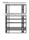
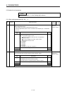
No. Symbol Name and function
Initial
value
[unit]
Setting
range
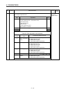
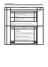
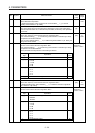
PA23 DRAT Drive recorder arbitrary alarm trigger setting Refer to the
"Name and
function" column.
Setting
digit
Explanation
Initial
value
_ _ x x Alarm detail No. setting
Set the digits when you execute the trigger with an arbitrary alarm
detail No. for the drive recorder function.
When these digits are "0 0", only the arbitrary alarm No. setting will
be enabled.
00h
x x _ _ Alarm No. setting
Set the digits when you execute the trigger with an arbitrary alarm
No. for the drive recorder function.
When "0 0" are set, the arbitrary alarm trigger of the drive recorder
will be disabled.
00h
Setting example:
To activate the drive recorder when [AL. 50 Overload 1] occurs, set "5 0 0 0".
To activate the drive recorder when [AL. 50.3 Thermal overload error 4 during operation]
occurs, set "5 0 0 3".
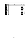
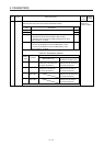
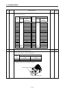
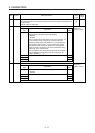
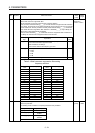
PA24 AOP4 Function selection A-4 Refer to the
"Name and
function" column.
Setting
digit
Explanation
Initial
value
_ _ _ x Vibration suppression mode selection
0: Standard mode
1: 3 inertia mode
2: Low response mode
When two low resonance frequencies are generated, select "3
inertia mode (_ _ _ 1)". When the load to motor inertia ratio exceeds
the recommended load to motor inertia ratio, select "Low response
mode (_ _ _ 2)".
When you select the standard mode or low response mode,
"Vibration suppression control 2" cannot be used.
When you select the 3 inertia mode, the feed forward gain cannot
be used.
Before changing the control mode with the controller during the 3
inertia mode or low response mode, stop the motor.
0h
_ _ x _ For manufacturer setting 0h
_ x _ _ 0h
x _ _ _ 0h