


1. FUNCTIONS AND CONFIGURATION
1 - 2
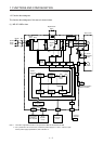
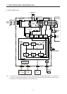
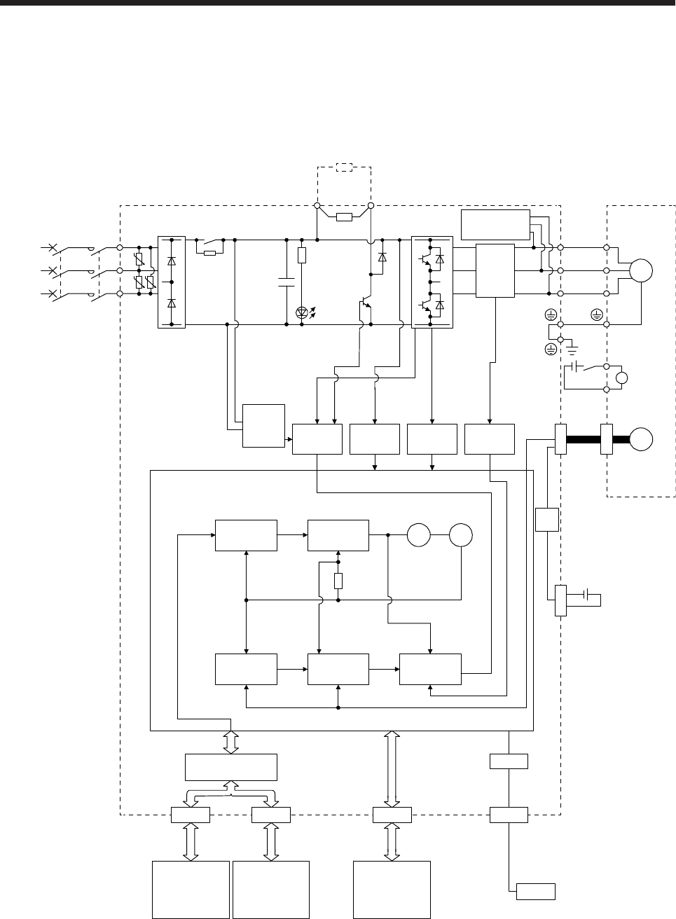
1.2 Function block diagram
The function block diagram of this servo is shown below.
(1) MR-JE-100B or less
MCMCCB
CN2
CN5
USB
USB
U U
U
C
L3
L2
L1
U
V
W
U
V
W
P+
+
B
RA
B1
B2
M
CN1A CN1B CN3
CN4
Model position
Current
control
Actual
position
control
Actual
speed
control
Virtual
motor
Virtual
encoder
Encoder
(Note 2)
Power
supply
Position
command
input
Model speed Model torque
Model
position
control
Model
speed
control
Servo motor
Dynamic
brake circuit
Current
detection
Overcurrent
protection
Voltage
detection
Base
amplifier
Diode
stack
Relay
(Note 1)
Control
circuit
power
CHARGE
lamp
Regene-
rative
TR
Current
detector
Regenerative
option
Personal
computer
Electro-
magnetic
brake
Servo system
controller or
servo amplifier
Servo
amplifier
or cap
Battery
(for absolute position
detection system)
Digital I/O
control
Step-
down
circuit
I/F Control
24 V DC
Note 1. The built-in regenerative resistor is not provided for MR-JE-10B and MR-JE-20B.
2. For 1-phase 200 V AC to 240 V AC, connect the power supply to L1 and L3. Leave L2 open.
For the power supply specifications, refer to section 1.3.