


6. NORMAL GAIN ADJUSTMENT
6 - 16
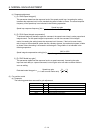
3) [Pr. PB08 Position loop gain]
This parameter determines the response level to a disturbance to the position control loop.
Increasing the position loop gain increases the response level to a disturbance, but the
mechanical system is liable to vibrate.
Position loop gain guideline ≤
(1 + Load to motor inertia ratio)
Speed loop gain
×
8
1
4
1
to
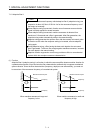
4) [Pr. PB07 Model loop gain]
This parameter determines the response level to a position command. Increasing the value
improves track ability to a position command, but too high a value will make overshoot liable to
occur at settling.
Estimated model loop gain ≤
(1 + Load to motor inertia ratio)
Speed loop gain
×
8
1
4
1
to
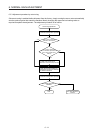
6.5 2 Gain adjustment mode
The 2 gain adjustment mode is used to match the position loop gains of the axes in the interpolation
operation of servo motors of two or more axes for an X-Y table or the like. In this mode, manually set the
model loop gain that determines command track ability. Other parameters for gain adjustment are set
automatically.
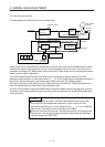
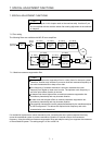
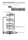
(1) 2 gain adjustment mode 1
For the 2 gain adjustment mode 1, manually set the model loop gain that determines command track
ability. The mode constantly estimates the load to motor inertia ratio, and automatically sets other
parameters for gain adjustment to optimum gains using auto tuning response.
The following parameters are used for 2 gain adjustment mode 1.
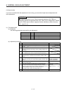
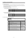
(a) Automatically adjusted parameter
The following parameters are automatically adjusted by auto tuning.
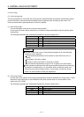
Parameter Symbol Name
PB06 GD2 Load to motor inertia ratio
PB08 PG2 Position loop gain
PB09 VG2 Speed loop gain
PB10 VIC Speed integral compensation
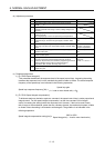
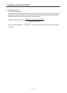
(b) Manually adjusted parameter
The following parameters are adjustable manually.
Parameter Symbol Name
PA09 RSP Auto tuning response
PB07 PG1 Model loop gain