


1. FUNCTIONS AND CONFIGURATION
1 - 9
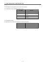
1.7 Structure
1.7.1 Parts identification
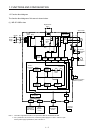
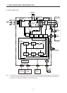
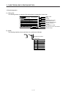
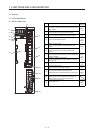
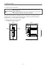
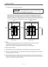
(1) MR-JE-100B or less
(1)
(2)
(6)
(9)
(5)
(4)
(3)
(7)
(8)
(10)
(12)
(11)
(13)
Side
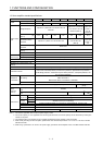
No. Name/Application
Detailed
explanation
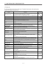
(1)
Display
The 3-digit, 7-segment LED shows the servo status and the
alarm number.
Section
4.3
(2)
Axis selection rotary switch (SW1)
Used to set the axis number of the servo amplifier.
(3)
USB communication connector (CN5)
Used to connect this connector to a personal computer.
Section
11.4
(4)
I/O signal connector (CN3)
Used to connect digital I/O signals.
Section
3.2
Section
3.4
(5)
Battery connector (CN4)
Used to connect the battery for absolute position data
backup.
Chapter
12
(6)
Battery holder
Used to house the battery for absolute position data
backup.
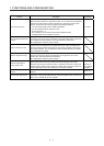
(7)
SSCNET III cable connector (CN1A)
Used to connect the servo system controller or the previous
axis servo amplifier.
Section
3.2
Section
3.4
(8)
SSCNET III cable connector (CN1B)
Used to connect the next axis servo amplifier. For the final
axis, put a cap.
(9)
Rating plate Section
1.6
(10)
Encoder connector (CN2)
Used to connect the servo motor encoder.
Section
3.4
(11)
Power connector (CNP1)
Used to connect the input power supply, built-in
regenerative resistor, regenerative option, and servo motor.
Section
3.1
Section
3.3
(12)
Charge lamp
When the main circuit is charged, this lamp will light up.
While this lamp is lit, do not reconnect the cables.
(13)
Protective earth (PE) terminal
Grounding terminal
Section
3.1
Section
3.3