


1. FUNCTIONS AND CONFIGURATION
1 - 11
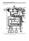
1.8 Configuration including peripheral equipment
CAUTION
Connecting a servo motor of the wrong axis to U, V, W, or CN2 of the servo
amplifier may cause a malfunction.
POINT
Equipment other than the servo amplifier and servo motor are optional or
recommended products.
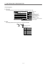
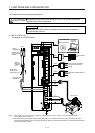
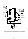
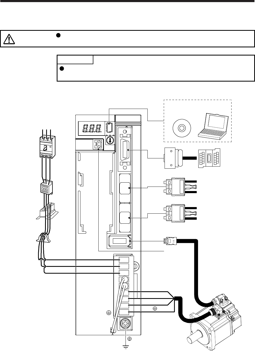
(1) MR-JE-100B or less
The diagram shows MR-JE-40B.
Power factor
improving AC
reactor (FR-HAL)
Line noise filter
(FR-BSF01)
Servo motor
Battery
Personal
computer
MR Configurator2
CN2
CN4
W
V
U
L1
L2
L3
(Note 2)
Magnetic
contactor
(MC)
Molded-case
circuit breaker
(MCCB)
RST
(Note 1)
Power supply
CN3
CN5
CN1A
CN1B
Junction terminal
block
Servo system controller or
previous servo amplifier
CN1B
Next servo amplifier CN1A or
cap
Note 1. For 1-phase 200 V AC to 240 V AC, connect the power supply to L1 and L3. Leave L2 open. For the power supply
specifications, refer to section 1.3.
2. Depending on the power supply voltage and operation pattern, bus voltage can decrease. This can shift the mode to the
dynamic brake deceleration during forced stop deceleration. When dynamic brake deceleration is not required, slow the time to
turn off the magnetic contactor.