


3. SIGNALS AND WIRING
3 - 13
3.3 Explanation of power supply system
3.3.1 Signal explanations
POINT
For the layout of the connector and terminal block, refer to chapter 9
DIMENSIONS.
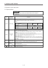
Symbol
Connection
destination
(application)
Description
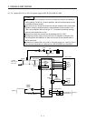
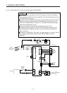
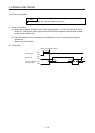
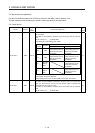
L1/L2/L3 Power supply
Supply the following power to L1, L2, and L3. For 1-phase 200 V AC to 240 V AC of MR-JE-10B to
MR-JE-100B, connect the power supply to L1 and L3. Leave L2 open.
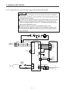
For 1-phase 200 V AC to 240 V AC of MR-JE-200B, connect the power supply to L1 and L2. Leave
L3 open.
Servo amplifier
Power supply
MR-JE-10B to
MR-JE-100B
MR-JE-200B MR-JE-300B
3-phase 200 V AC to 240 V AC,
50 Hz/60 Hz
L1/L2/L3
1-phase 200 V AC to 240 V AC,
50 Hz/60 Hz
L1/L3 L1/L2
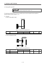
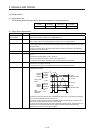
P+/C/D
Regenerative
option
1) MR-JE-100B or less
MR-JE-10B to MR-JE-100B do not have D.
When using a servo amplifier built-in regenerative resistor, connect it to P+ and C. (factory-
wired)
MR-JE-10B and MR-JE-20B do not have a built-in regenerative resistor.
When using a regenerative option, disconnect wires of the built-in regenerative resistor from P+
and C. Then, connect wires of the regenerative option to P+ and C.
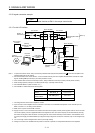
2) MR-JE-200B or more
When using a servo amplifier built-in regenerative resistor, connect P+ and D. (factory-wired)
When using a regenerative option, disconnect P+ and D, and connect the regenerative option to
P+ and C.
Refer to section 11.2 for details.
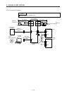
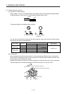
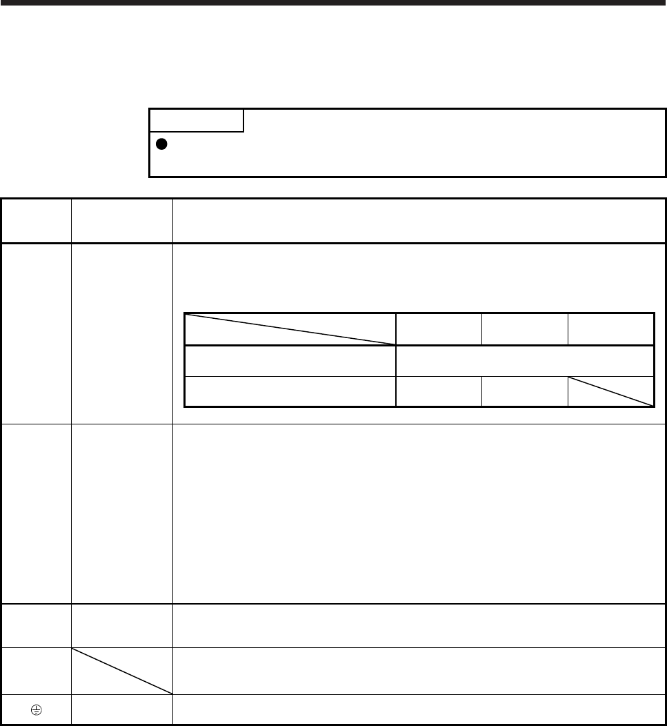
U/V/W
Servo motor
power output
Connect the terminals to the servo motor power supply terminals (U, V, and W). Connect the servo
amplifier power output (U, V, and W) to the servo motor power input (U, V, and W) directly. Do not
let a magnetic contactor, etc. intervene. Otherwise, it may cause a malfunction.
N-
This terminal is for manufacturer adjustment.
Leave this terminal open.
MR-JE-10B to MR-JE-100B do not have N-.
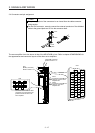
Protective earth
(PE)
Connect this terminal to the grounding terminal of the servo motor and to the protective earth (PE)
of the cabinet for grounding.