3. SIGNALS AND WIRING
3 - 12
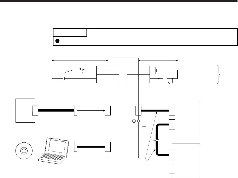
3.2.2 For source I/O interface
POINT
For notes, refer to section 3.2.1.
10
20EM2
CN3 CN3
13 MBR
RA1
DICOM
CN5
MR Configurator2
+
MR-J3USBCBL3M
CN1A
CN1B
CN1A
CN1B
CN1BCN1A
3
DOCOM
Servo amplifier
(Note 11)
Electromagnetic brake
interlock
(Note 12)
Power supply
(Note 10) 24 V DC
10 m or less
10 m or less
Servo amplifier
(Note 3, 4)
Forced stop 2
Personal
computer(Note 5)
USB cable
(option)
(Note 6)
SSCNET III cable
(option)
Servo system
controller
(Note 7)
(Note 1)
(Note 9)
Cap
The last servo amplifier (Note 8)
(Note 6)
SSCNET III cable
(option)
(Note 7)
24 V DC (Note 10)
(Note 2)


