


3. SIGNALS AND WIRING
3 - 11
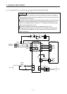
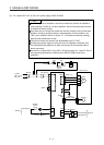
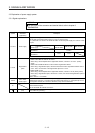
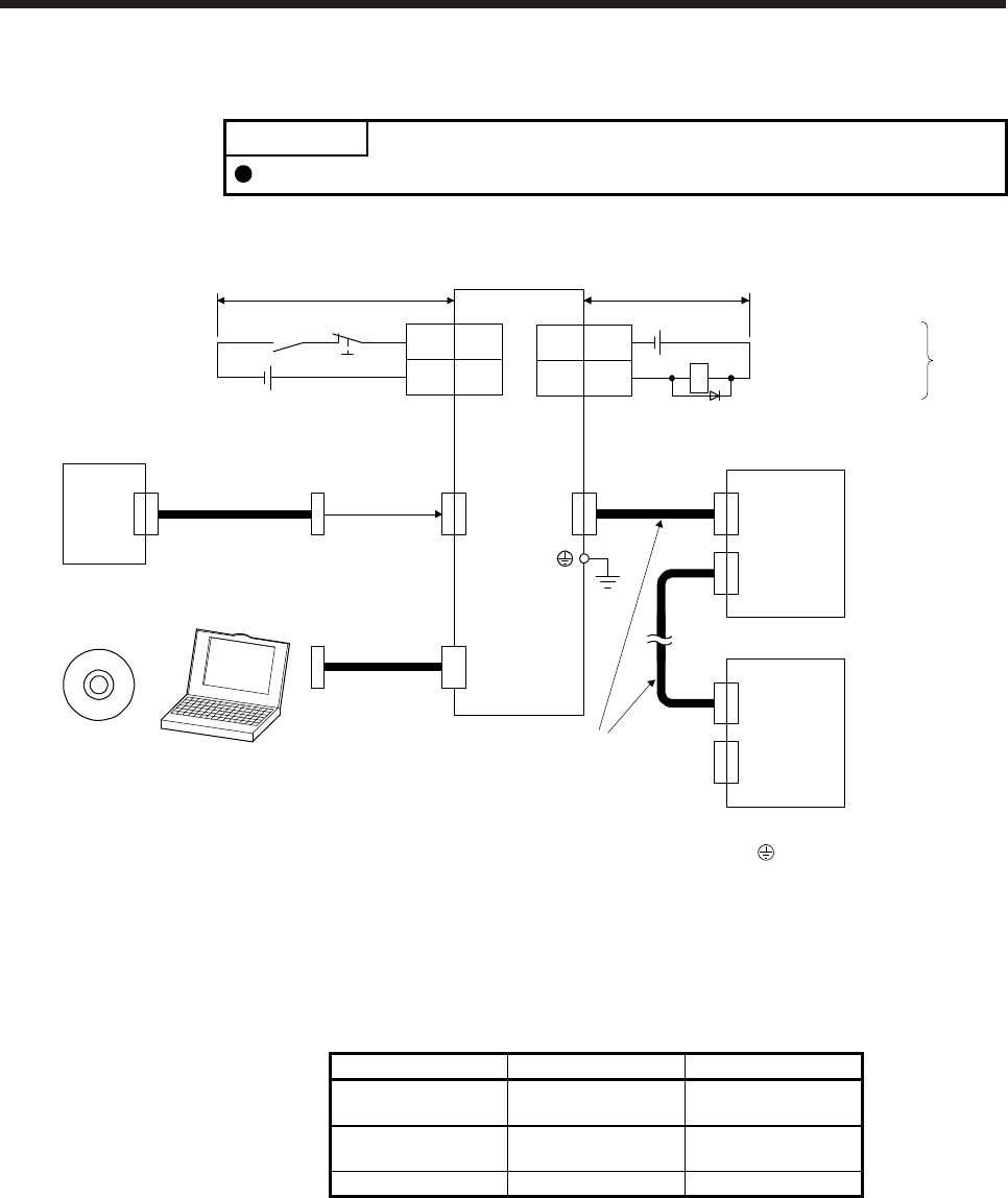
3.2 I/O signal connection example
POINT
EM2 has the same function as EM1 in the torque control mode.
3.2.1 For sink I/O interface
20EM2
10
Servo amplifie
r
CN3
(Note 11)
CN3
Electromagnetic brake
interlock
13 MBR
RA1
DOCOM
DICOM
3
(Note 12)
Power supply
(Note 10) 24 V DC
10 m or less
10 m or less
Servo amplifier
(Note 3, 4)
Forced stop 2
Personal
computer
CN5
(Note 5)
MR Configurator2
+
USB cable
MR-J3USBCBL3M
(option)
(Note 6)
SSCNET III cable
(option)
Servo system
controller
CN1A
CN1B
(Note 7)
(Note 1)
(Note 9)
Cap
CN1A
CN1B
The last servo amplifier (Note 8)
CN1BCN1A
(Note 6)
SSCNET III cable
(option)
(Note 7)
24 V DC (Note 10)
(Note 2)
Note 1. To prevent an electric shock, always connect the protective earth (PE) terminal (marked with ) of the servo amplifier to the
protective earth (PE) of the cabinet.
2. Connect the diode in the correct direction. If it is connected reversely, the servo amplifier will malfunction and will not output
signals, disabling EM2 (Forced stop 2) and other protective circuits.
3. If the controller does not have a forced stop function, always install the forced stop 2 switch (normally closed contact).
4. When starting operation, always turn on EM2 (Forced stop 2). (normally closed contact)
5. Use SW1DNC-MRC2-E. (Refer to section 11.4.)
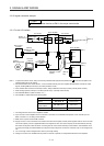
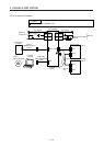
6. Use SSCNET III cables listed in the following table.
Cable Cable model Cable length
Standard cord inside
cabinet
MR-J3BUS_M 0.15 m to 3 m
Standard cable
outside cabinet
MR-J3BUS_M-A 5 m to 20 m
Long distance cable MR-J3BUS_M-B 30 m to 50 m
7. The wiring after the second servo amplifier is omitted.
8. Up to 16 axes of servo amplifiers can be connected. The number of connectable axes depends on the controller you use.
Refer to section 4.3.1 for setting of axis selection.
9. Make sure to cap the unused CN1B connector.
10. Supply 24 V DC ± 10% to interfaces from outside. The total current capacity of these power supplies must be 100 mA or lower.
The current capacity 100 mA is applicable when all I/O signals are used. The current capacity can be decreased by reducing
the number of I/O points. Refer to section 3.8.2 that gives the current value necessary for the interface. The illustration of the
24 V DC power supply is divided between input signal and output signal for convenience. However, they can be configured by
one.
11. You can change a device assigned to the CN3-13 pin with [Pr. PD07].
12. Configure a circuit to turn off EM2 when the power is turned off to prevent an unexpected restart of the servo amplifier.