


3. SIGNALS AND WIRING
3 - 17
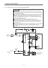
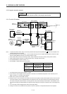
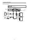
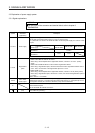
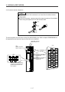
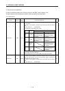
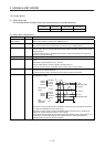
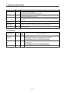
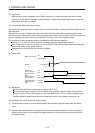
3.4 Connectors and pin assignment
POINT
The pin assignment of the connectors is as viewed from the cable connector
wiring section.
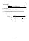
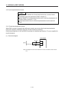
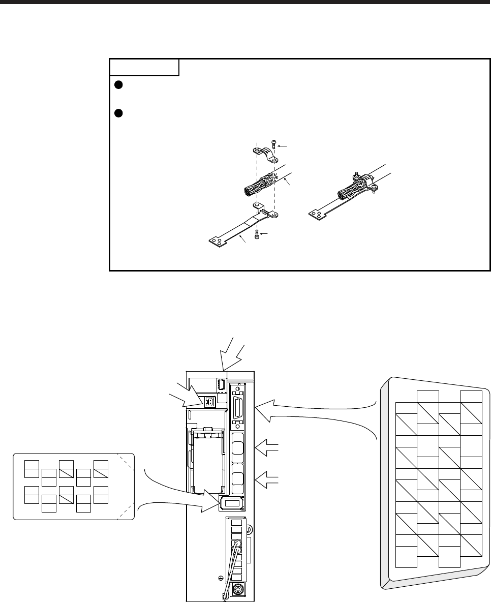
For the CN3 connector, securely connect the external conductor of the shielded
cable to the ground plate and fix it to the connector shell.
Screw
Screw
Ground plate
Cable
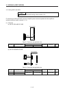
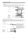
The servo amplifier front view shown is that of the MR-JE-40B or less. Refer to chapter 9 DIMENSIONS for
the appearances and connector layouts of the other servo amplifiers.
CN5 (USB connector)
Refer to section 11.4.
CN3
The frames of the CN2 and CN3
connectors are connected to the
protective earth terminal in the
servo amplifier.
CN1A
Connector for SSCNET III
cable for previous servo
amplifier axis
CN1B
Connector for SSCNET III
cable for next servo
amplifier axis
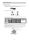
1
2
3
5
4
6
7
9
8
10
11
12
13
14
15
16
17
18
19
20
DICOM
DOCOM
EM2
MBR
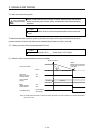
4
MRR
2
LG 8
6
1
P5
5
10
3
MR
7
9
BAT
MDR
MD
CN2
CN4
(Battery connector)
Refer to section 11.5.