


3. SIGNALS AND WIRING
3 - 4
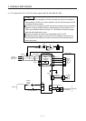
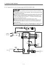
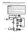
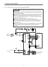
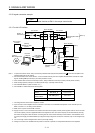
Note 1. MR-JE-40B to MR-JE-100B have a built-in regenerative resistor. (factory-wired) When using the regenerative option, refer to
section 11.2.
2. For the encoder cable, use of the option cable is recommended. For cable selection, refer to "HG-KN_/HG-SN_ Servo Motor
Instruction Manual".
3. This diagram is for the sink I/O interface. For source I/O interface, refer to section 3.8.3.
4. For connection of servo motor power wires, refer to "HG-KN_/HG-SN_ Servo Motor Instruction Manual".
5. Configure the power supply circuit that turns off the magnetic contactor after an alarm occurs on the controller side.
6. Configure a circuit to turn off EM2 when the power is turned off to prevent an unexpected restart of the servo amplifier.
7. Connecting a servo motor of the wrong axis to U, V, W, or CN2 of the servo amplifier may cause a malfunction.
8. Use a magnetic contactor with an operation delay time (interval since a current is applied to the coil until the contact closes) of
80 ms or shorter. Depending on the power supply voltage and operation pattern, bus voltage can decrease. This can shift the
mode to the dynamic brake deceleration during forced stop deceleration. When dynamic brake deceleration is not required,
slow the time to turn off the magnetic contactor.
9. The illustration of the 24 V DC power supply is divided between input signal and output signal for convenience. However, they
can be configured by one.