


11. OPTIONS AND PERIPHERAL EQUIPMENT
11 - 36
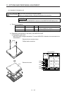
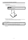
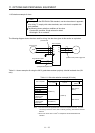
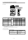
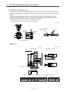
(2) Dimensions
4-d mounting hole
(Varnish is removed from front right mounting
hole (face and back side).) (Note 1)
Terminal layout
RX ZSYT
Max. W (Note 2)
W1
D1
D2
H
D or less
Fig. 11.1
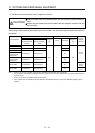
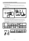
Servo amplifier
Power factor
improving AC
reactor
Dimensions
Dimensions [mm]
Terminal
size
Mass
[kg]
W W1 H
D
(Note 3)
D1 D2 d
MR-JE-10B, MR-JE-20B FR-HAL-0.4K
Fig. 11.1
104 84 99 72 51 40 M5 M4 0.6
MR-JE-40B FR-HAL-0.75K 104 84 99 74 56 44 M5 M4 0.8
MR-JE-70B FR-HAL-1.5K 104 84 99 77 61 50 M5 M4 1.1
MR-JE-100B
(3-phase power supply input)
FR-HAL-2.2K
115
(Note 3)
40 115 77 71 57 M6 M4 1.5
MR-JE-100B
(1-phase power supply input)
MR-JE-200B
(3-phase power supply input)
FR-HAL-3.7K
115
(Note 3)
40 115 83 81 67 M6 M4 2.2
MR-JE-200B
(1-phase power supply input)
MR-JE-300B
FR-HAL-5.5K
115
(Note 3)
40 115 83 81 67 M6 M4 2.3
Note 1. Use this for grounding.
2. W ± 2 is applicable for FR-HAL-0.4K to FR-HAL-1.5K.
3. Maximum dimensions. The dimension varies depending on the input/output lines.
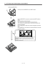
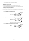
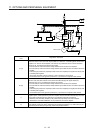
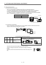
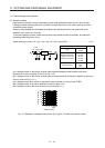
11.9 Relay (recommended)
The following relays should be used with the interfaces.
Interface Selection example
Digital input (interface DI-1)
Relay used for digital input command signals
To prevent defective contacts, use a relay for
small signal (twin contacts).
(Ex.) Omron: type G2A, MY
Digital output (interface DO-1)
Relay used for digital output signals
Small relay with 12 V DC or 24 V DC of rated
current 40 mA or less
(Ex.) Omron: type MY