


7. SPECIAL ADJUSTMENT FUNCTIONS
7 - 17
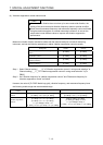
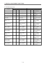
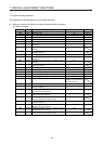
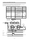
(a) [Pr. PB06] to [Pr. PB10]
These parameters are the same as in ordinary manual adjustment. Gain switching allows the values
of load to motor inertia ratio, position loop gain, speed loop gain, and speed integral compensation to
be switched.
(b) [Pr. PB19] to [Pr. PB22]/[Pr. PB52] to [Pr. PB55]
These parameters are the same as in ordinary manual adjustment. You can switch the vibration
frequency, resonance frequency, vibration frequency damping, and resonance frequency damping
by switching gain during motor stop.
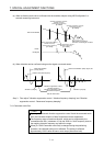
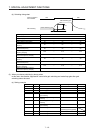
(c) [Pr. PB29 Load to motor inertia ratio after gain switching]
Set the load to motor inertia ratio after gain switching. If the load to motor inertia ratio does not
change, set it to the same value as [Pr. PB06 Load to motor inertia ratio].
(d) [Pr. PB30 Position loop gain after gain switching], [Pr. PB31 Speed loop gain after gain switching],
and [Pr. PB32 Speed integral compensation after gain switching]
Set the values of after switching position loop gain, speed loop gain and speed integral
compensation.
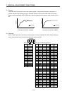
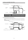
(e) Vibration suppression control after gain switching ([Pr. PB33] to [Pr. PB36]/[Pr. PB56] to [Pr.
PB59])/[Pr. PB60 Model loop gain after gain switching]
The gain switching vibration suppression control and model loop gain are used only with a control
command from the controller.
You can switch the vibration frequency, resonance frequency, vibration frequency damping,
resonance frequency damping, and model loop gain of the vibration suppression control 1 and
vibration suppression control 2.