


4. STARTUP
4 - 2
4.1.2 Wiring check
(1) Power supply system wiring
Before switching on the power supply, check the following items.
(a) Power supply system wiring
The power supplied to the power input terminals (L1, L2, and L3) of the servo amplifier should satisfy
the defined specifications. (Refer to section 1.3.)
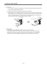
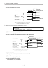
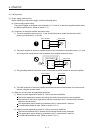
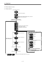
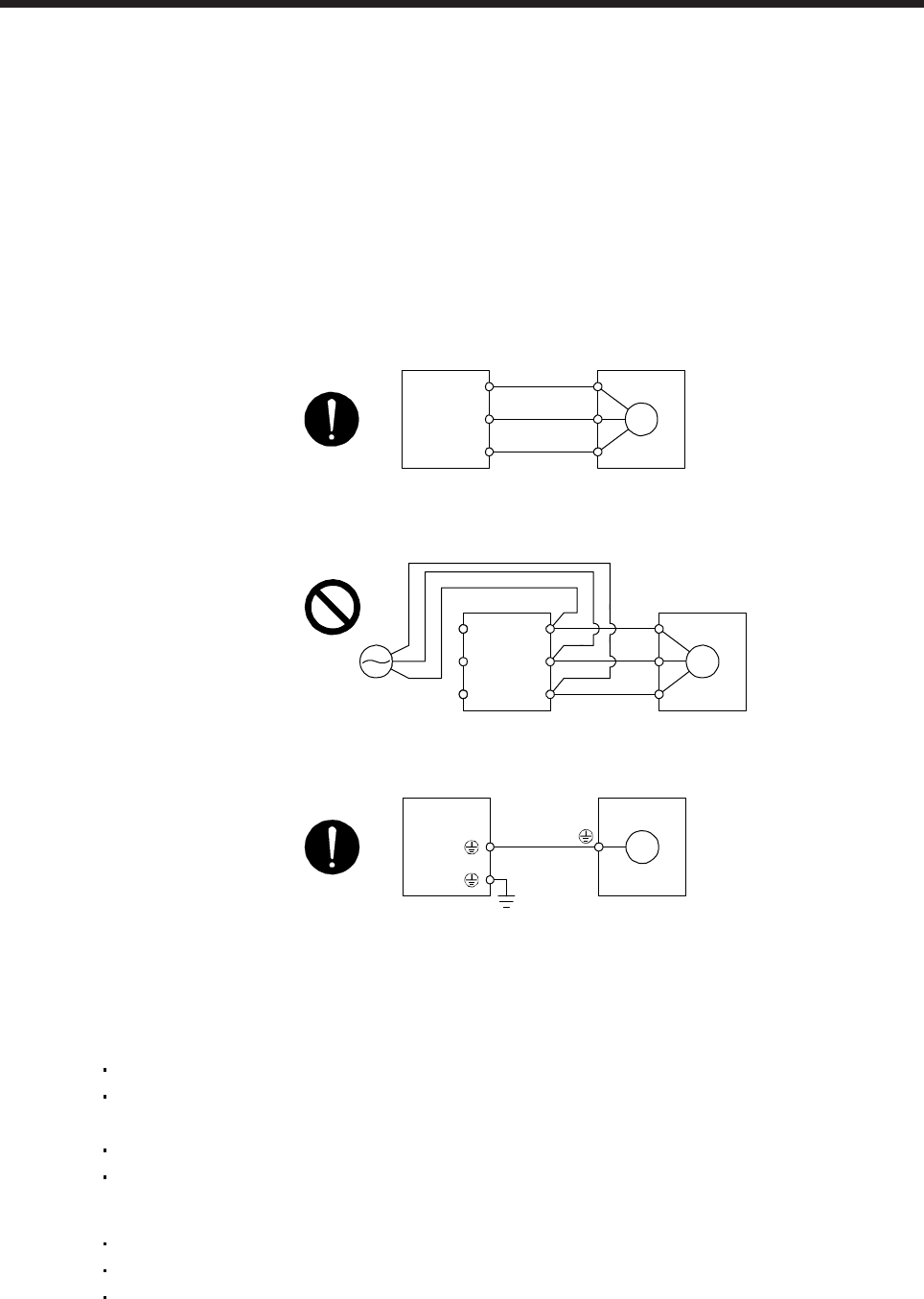
(b) Connection of the servo amplifier and servo motor
1) The servo amplifier power output (U, V, and W) should match in phase with the servo motor
power input terminals (U, V, and W).
Servo amplifie
r
Servo moto
r
M
U
V
W
U
V
W
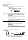
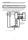
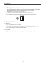
2) The power supplied to the servo amplifier should not be connected to the power output (U, V, and
W). Doing so will cause failure of the connected servo amplifier and servo motor.
Servo amplifier Servo motor
M
U
V
W
U
V
W
L1
L2
L3
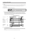
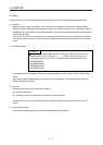
3) The grounding terminal of the servo motor is connected to the PE terminal of the servo amplifier.
Servo amplifier Servo motor
M
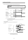
4) The CN2 connector of the servo amplifier should be connected to the encoder of the servo motor
securely using the encoder cable.
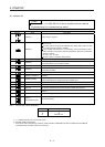
(c) When you use an option and peripheral equipment
1) When you use a regenerative option for 1 kW or less servo amplifiers
The built-in regenerative resistor and wirings should be removed from the servo amplifier.
The lead wire of the built-in regenerative resistor connected to the P+ terminal and C terminal
should not be connected.
The regenerative option should be connected to the P+ terminal and C terminal.
A twisted cable should be used. (Refer to section 11.2.4.)
2) When you use a regenerative option for 2 kW or more servo amplifiers
The lead wire between the P+ terminal and D terminal should not be connected.
The regenerative option should be connected to the P+ terminal and C terminal.
A twisted cable should be used. (Refer to section 11.2.4.)