


3. SIGNALS AND WIRING
3 - 18
3.5 Signal (device) explanations
For the I/O interfaces (symbols in I/O division column in the table), refer to section 3.8.2.
The pin numbers in the connector pin number column are those in the initial status.
3.5.1 Input device
Device Symbol
Connector
pin
number
Function and application
I/O
division
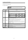
Forced stop 2 EM2 CN3-20
Turn off EM2 (open between commons) to decelerate the servo motor to a stop
with commands.
Turn EM2 on (short between commons) in the forced stop state to reset that
state.
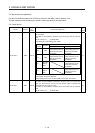
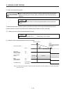
Set [Pr. PA04] to "2 1 _ _" to disable EM2.
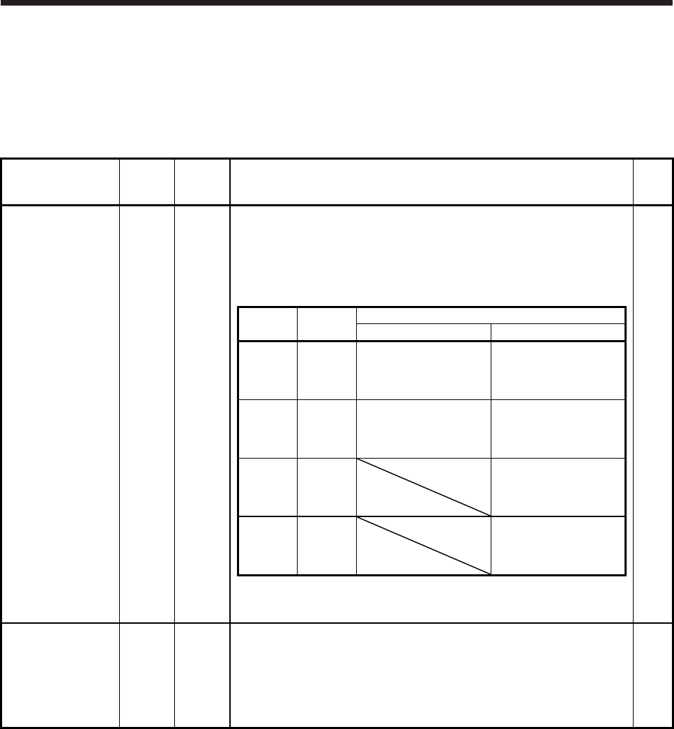
The following shows the setting of [Pr. PA04].
DI-1
[Pr. PA04]
setting
EM2/EM1
Deceleration method
EM2 or EM1 is off Alarm occurred
0 0 _ _ EM1
MBR (Electromagnetic
brake interlock) turns off
without the forced stop
deceleration.
MBR (Electromagnetic
brake interlock) turns off
without the forced stop
deceleration.
2 0 _ _ EM2
MBR (Electromagnetic
brake interlock) turns off
after the forced stop
deceleration.
MBR (Electromagnetic
brake interlock) turns off
after the forced stop
deceleration.
0 1 _ _
Not using
EM2 or
EM1
MBR (Electromagnetic
brake interlock) turns off
without the forced stop
deceleration.
2 1 _ _
Not using
EM2 or
EM1
MBR (Electromagnetic
brake interlock) turns off
after the forced stop
deceleration.
EM2 and EM1 are mutually exclusive.
Note that EM2 has the same function as EM1 in the torque control mode.
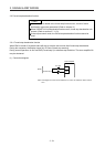
Forced stop 1 EM1 (CN3-20)
When using EM1, set [Pr. PA04] to "0 0 _ _" to enable EM1.
Turn EM1 off (open between commons) to bring the motor to a forced stop
state. The base circuit is shut off, and the dynamic brake is operated and
decelerates the servo motor to a stop.
Turn EM1 on (short between commons) in the forced stop state to reset that
state.
Set [Pr. PA04] to "0 1 _ _" to disable EM1.
DI-1