


4. STARTUP
4 - 5
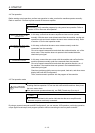
(5) Stop
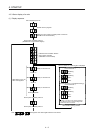
If any of the following situations occurs, the servo amplifier suspends the running of the servo motor and
brings it to a stop.
Refer to section 3.10 for the servo motor with an electromagnetic brake.
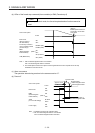
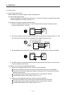
Operation and command Stopping condition
Servo system
controller
Servo-off command The base circuit is shut off and the servo motor coasts.
Ready-off command
The base circuit is shut off and the dynamic brake operates to
bring the servo motor to a stop.
Forced stop command
The servo motor decelerates to a stop with the command. [AL.
E7 Controller forced stop warning] occurs.
Servo amplifier
Alarm occurrence
The servo motor decelerates to a stop with the command. With
some alarms, however, the dynamic brake operates to bring the
servo motor to a stop. (Refer to chapter 8. (Note))
EM2 (Forced stop 2) off
The servo motor decelerates to a stop with the command. [AL.
E6 Servo forced stop warning] occurs. EM2 has the same
function as that of EM1 in the torque control mode.
Note. Only a list of alarms and warnings is listed in chapter 8. Refer to "MELSERVO-JE Servo Amplifier
Instruction Manual (Troubleshooting)" for details of alarms and warnings.
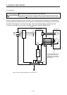
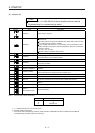
4.3 Switch setting and display of the servo amplifier
The control axis No. can be set with switches on the servo amplifier.
On the servo amplifier display (three-digit, seven-segment LED), check the status of communication with the
servo system controller at power-on and the axis number, and diagnose a malfunction at occurrence of an
alarm.
4.3.1 Axis selection rotary switch (SW1)
WARNING
When switching the axis selection rotary switch (SW1), use an insulated screw
driver. Do not use a metal screw driver. Touching patterns on electronic boards,
lead of electronic parts, etc. may cause an electric shock.
POINT
The control axis No. set to the axis selection rotary switch (SW1) should be the
same as the one set to the servo system controller. The number of the axes you
can set depends on the servo system controller.
For setting the axis selection rotary switch, use a flat head screwdriver with the
blade edge width of 2.1 mm to 2.3 mm and the blade edge thickness of 0.6 mm
to 0.7 mm.
Cycling the power supply enables the setting of the switch.