


3. SIGNALS AND WIRING
3 - 38
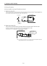
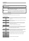
(2) Setting
In [Pr. PC02 Electromagnetic brake sequence output], set a delay time (Tb) from MBR (Electromagnetic
brake interlock) off to base circuit shut-off at a servo-off as in the timing chart in section 3.10.2.
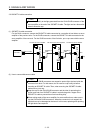
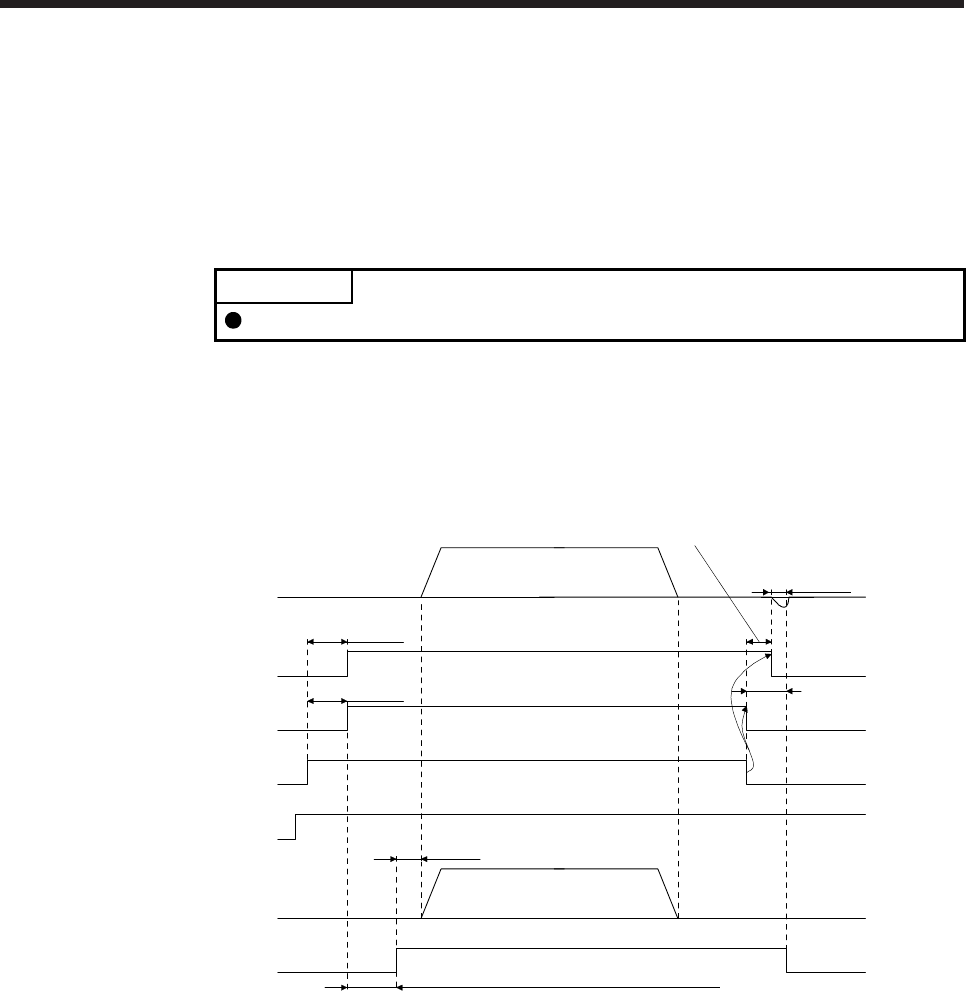
3.10.2 Timing chart
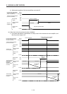
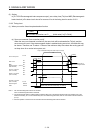
(1) When you use the forced stop deceleration function
POINT
To enable the function, set "2 _ _ _ (initial value)" in [Pr. PA04].
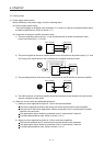
(a) Servo-on command (from controller) on/off
When the servo-on command is turned off, the servo lock will be released after Tb [ms], and the
servo motor will coast. If the electromagnetic brake is enabled during servo-lock, the brake life may
be shorter. Therefore, set Tb about 1.5 times of the minimum delay time where the moving part will
not drop down for a vertical axis system, etc.
Approx. 95 ms
Approx. 95 ms
MBR
(Electromagnetic
brake interlock)
(Note 1)
ON
OFF
ON
OFF
0 r/min
Base circuit
Servo motor speed
Coasting
Operation delay time of
the electromagnetic brake
Ready-on command
(from controller)
ON
OFF
Release
Activate
Operation command
(from controller)
Electromagnetic
brake
Release delay time and external relay, etc. (Note 2)
(Note 3)
0 r/min
Servo-on command
(from controller)
ON
OFF
Tb [Pr. PC02 Electromagnetic brake sequence output]
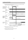
Note 1. ON: The electromagnetic brake is not activated.
OFF: The electromagnetic brake is activated.
2. The electromagnetic brake is released after the release delay time of the electromagnetic brake and operation time of the
external circuit relay, etc. For the release delay time of the electromagnetic brake, refer to "Servo Motor Instruction Manual
(Vol. 3)".
3. Give the operation command from the controller after the electromagnetic brake is released.